Chain drive for link chains of mining conveyors or mining extraction machines

a technology of mining conveyors and chain drives, which is applied in the direction of conveyors, gearing details, portability lifting, etc., can solve the problems of affecting the the sprocket is subject to a heavy bending load, and the screwing into the place of the sprocket halves requires very strong screws, so as to ensure the necessary stability of the sprocket tooth body and ensure the effect of force delivery

Active Publication Date: 2018-01-09
HALBACH & BRAUN MASCHFAB GMBH CO
View PDF21 Cites 0 Cited by
  • Summary
  • Abstract
  • Description
  • Claims
  • Application Information

AI Technical Summary

Benefits of technology

[0031]The elimination of the need for a separate sprocket makes it possible to make seats in the drive shaft despite the small amount of space for installation. The seats have a depth that ensures that the sprocket tooth bodies or the lower coupling sections of the sprocket tooth bodies are held in place securely with a snug fit and without any play. The seats have a correspondingly large depth. The sprocket tooth bodies are inserted into the seats with their coupling sections. The part of the sprocket tooth body protruding in relation to the circumference of the drive shaft has a free tooth height. This free tooth height is measured between the outer circumference of the drive shaft and the line of action of

Problems solved by technology

Within this pitch circle diameter, there is only limited space for installation of the shaft cross-section and the sprocket.
Similarly, the chain teeth on the sprocket are subjected to a heavy bending load due to the tensile forces exerted on the chain.
A disadvantage is that the screwing into place of the sprocket halves requires very strong screws which must be tightened with heavy tools (torque amplifier).
The chain rings with internal teeth for torque absorption are also very expensive.
Generally, it should be noted that the screw connection of the sprocket halves with each other and the sprocket on the shaft is problematic, especially for very strong mining chains with wire diameters of up to 60 mm and maximum tensile forces of 4,500 kN to 5,000 kN.
The necessary screws require a large amount of space for installation and therefore a minimum width of the sprocket.
This makes i

Method used


Image

  • Chain drive for link chains of mining conveyors or mining extraction machines
  • Chain drive for link chains of mining conveyors or mining extraction machines

Examples


Embodiment Construction

[0037]Further scope of applicability of the present invention will become apparent from the detailed description given hereinafter. However, it should be understood that the detailed description and specific examples, while indicating preferred embodiments of the invention, are given by way of illustration only, since various changes and modifications within the spirit and scope of the invention will become apparent to those skilled in the art from this detailed description.

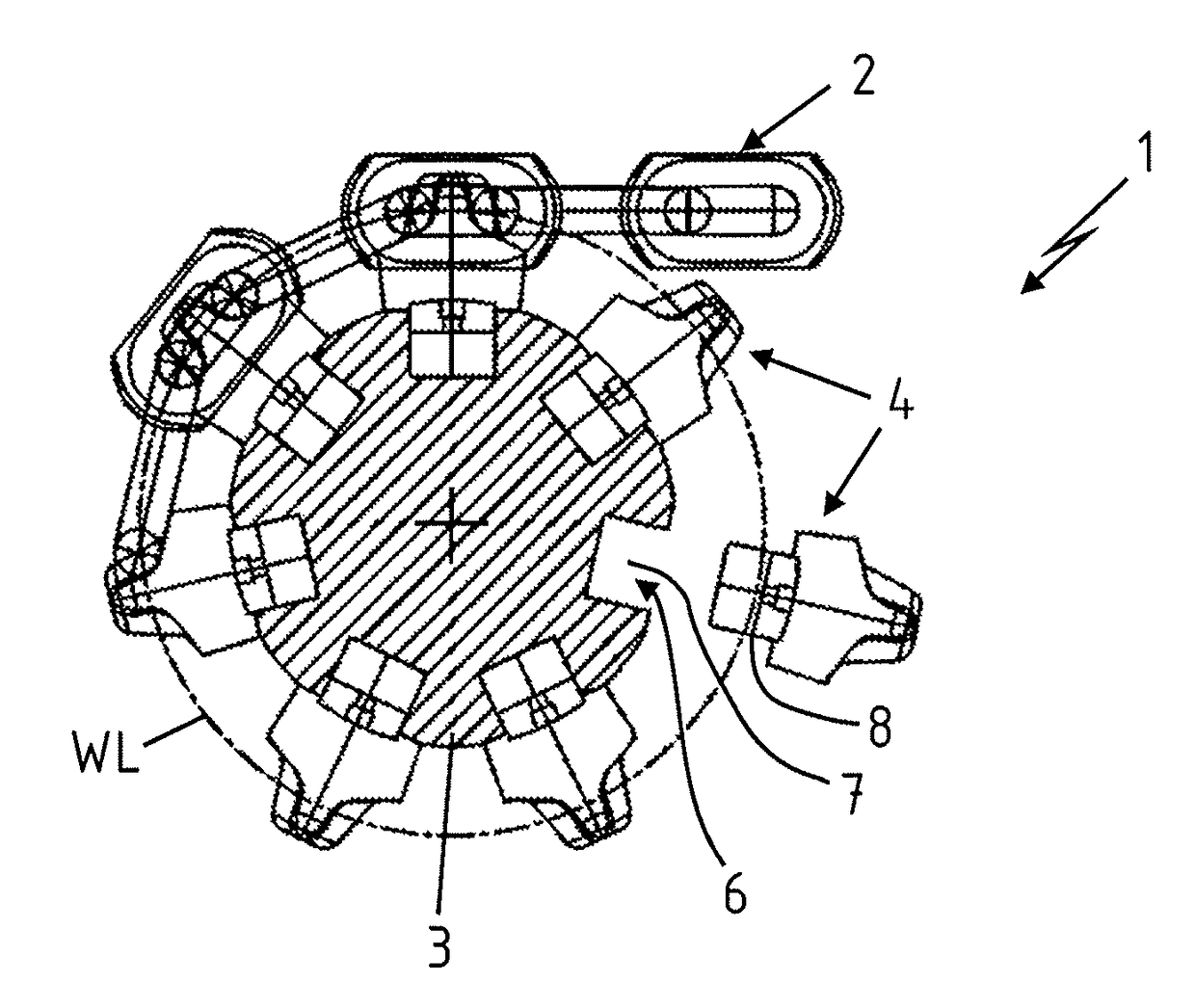
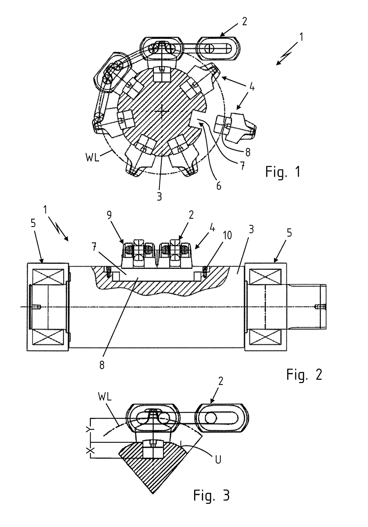
[0038]Based on FIGS. 1 to 3, a chain drive 1 according to the invention is explained. The chain drive 1 is used to drive a link chain 2 of a scraper chain conveyor.

[0039]The chain drive 1 comprises a drive shaft 3 and sprocket tooth bodies 4 arranged on its circumference. The drive shaft 3 is supported by bearings 5 in a machine frame, not shown here.

[0040]As can be seen in FIG. 1, a total of seven sprocket tooth bodies 4 are envisaged in the embodiment represented here. The sprocket tooth bodies 4 are set into s...


PUM


Abstract

A chain drive for a link chain of mining conveyors or mining extraction machines, in particular for scraper chain conveyors, includes a drive shaft. The drive power or the drive torque is introduced into the link chain by chain tooth elements. The chain tooth elements are set directly in the drive shaft in seats. For that purpose, the chain tooth elements have a lower coupling portion for interlocking engagement in the seats in the drive shaft. Accordingly, a separate chain wheel is unnecessary.

Description

CROSS-REFERENCE TO RELATED APPLICATION[0001]This application is a national stage of PCT / DE2013 / 100159, filed Apr. 30, 2013, and published in German.BACKGROUND OF THE INVENTION[0002]1. Field of Invention[0003]The invention relates to a chain drive for link chains of mining conveyors or mining extraction machines, in particular for scraper chain conveyors, with a drive shaft and sprocket tooth bodies.[0004]2. Description of the Prior Art[0005]Chain drives are used in mining operations, especially in chain conveyors, in particular scraper chain conveyors, and for powering mining extraction machines, especially coal plows and the like.[0006]Chain conveyors are continuous conveyors and are the preferred means of conveyance, especially in the hard coal mining industry. The material to be conveyed is in this case moved by carriers (scrapers), which are fastened to electric motor-driven endless chains, in a conveyor trough.[0007]A scraper chain conveyor is mainly composed of a drive station...

Claims


Application Information

Patent Timeline
IPC IPC(8): B65G23/06F16H57/00F16H55/30F16H55/10
CPCB65G23/06F16H57/0025F16H55/30F16H55/10
Inventor BRAUN, DIETRICHBRAUN, EBERHARD
Owner HALBACH & BRAUN MASCHFAB GMBH CO
Why Eureka
Try Eureka