
Multiple piece construction automotive door hinge

a technology of automotive doors and hinges, applied in the field of hinges, can solve problems such as material interference and create, and achieve the effect of reducing or eliminating scrapping

Active Publication Date: 2018-01-09
MULTIMATIC INC
View PDF47 Cites 5 Cited by
  • Summary
  • Abstract
  • Description
  • Claims
  • Application Information

AI Technical Summary

Benefits of technology

[0007]Accordingly, it would be advantageous to create a hinge assembly that is constructed utilizing press formed metal stampings but which reduces or eliminates the scrap associated with the complex shapes dictated by a vehicle's closure panel and body configuration. A great deal of the material used and scrapped in the press forming of a hinge component is directly attributable to shape complexity dictated by the required distances between the mounting holes and pivot pin support features. It would therefore be a significant improvement over the existing art if the interconnection of these features could be achieved in a more efficient manner.
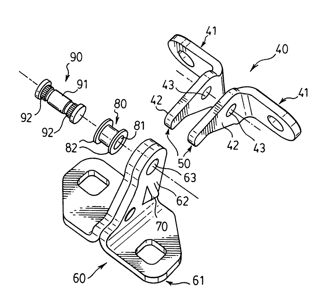
[0008]The present invention is targeted at reducing the total material utilized in press formed metal stamped hinge components by utilizing the pivot pin as a primary structural component. In a conventionally configured automotive door hinge utilizing a single piece door component and single piece body component, the pivot pin performs two primary functions in that it structurally assembles the two components while facilitating relative rotary motion between them. The present invention utilizes the pivot pin for an additional primary function in that it also structurally connects multiple pieces of each individual component. A conventionally manufactured single piece press formed door component normally connects its two mounting surfaces and two pivot arms via an integral structural bridge. The present invention eliminates the structural bridge and configures each mounting surface and associated pivot arm as an individual separate press formed angle bracket and structurally connects two of these angle brackets together using a uniquely configured pivot pin. Additionally, the present invention utilizes a unique body component configured from two simple press formed angle brackets that are structurally connected via a simple formed feature and the pivot pin.
[0009]The pivot pin of the present invention is configured with a central cylindrical pivot surface and two knurled opposing cylindrical ends stepped down in diameter from the central cylindrical pivot surface. The two press formed angle brackets of the body component are structurally connected via a simple formed feature on the pivot arms and a single pivot bushing is assembled in the pivot holes via a flanged arrangement. The pivot pin is arranged within the pivot bushing so that the central cylindrical pivot surface can freely rotate and the press formed angle brackets of the door component are configured to be structurally connected to the knurled opposing cylindrical ends of the pivot pin via riveting, staking or similar means of material upsetting.
[0011]In another alternative embodiment of the present invention, the pivot pin is configured with a cantilevered feature to facilitate simple separation and reassembly of the door and body components as required in some vehicle assembly plants.
[0016]In accordance with further aspects of this invention, an automotive hinge assembly as described, wherein the pivot pin is configured to structurally connect the press formed door angle brackets via a pivot bushing, washer and material upset while providing a cantilevered feature to facilitate simple separation and reassembly of the door and body components using a tapered nut and tapered pivot hole arrangement.

Problems solved by technology

A great deal of the material used and scrapped in the press forming of a hinge component is directly attributable to shape complexity dictated by the required distances between the mounting holes and pivot pin support features.
The material interference that creates the structural connection occurs between the tapered step and press formed angle brackets of the door components.

Method used


Image

  • Multiple piece construction automotive door hinge

Examples


Embodiment Construction

[0032]Referring to FIGS. 3, 4, 5, and 6, an automotive hinge assembly (30) is substantially constructed from a door component (40) and a body component (60). The door component is configured with a mounting surface (41) and two pivot arms (42). Each pivot arm (42) contains a pivot axis hole (43). The door component (40) is structurally attached to a vehicle closure panel (27) via its mounting surface (41) using bolting, welding, bonding, riveting or similar fastening means. The body component (60) is configured with a mounting surface (61) and a pivot arm (62). The pivot arm (62) contains a pivot axis hole (63). The body component is structurally attached to a vehicle body structure (28) via its mounting surface (61) using bolting, welding, bonding, riveting or similar fastening means. The pivot axis hole (63) of the body component (60) is fitted with a pivot bushing (80) that contains an internal cylindrical bearing surface (81) and two opposing thrust flanges (82). Referring to FI...


PUM


Abstract

An automotive hinge assembly adapted to facilitate motion of a closure panel relative to a fixed body structure comprises a door component constructed from two press formed angle brackets structurally connected via a pivot pin and adapted to be mounted to a vehicle closure panel, a body component constructed from two press formed angle brackets structurally connected via a simple formed feature and the pivot pin and adapted to be mounted to a vehicle body structure, such that the pivot pin structurally assembles the two hinge components, facilitates relative rotary motion between them and structurally connects the multiple press formed angle brackets so that the resulting assembly achieves a much higher material efficiency than the prior art with an associated significant cost reduction.

Description

RELATED APPLICATIONS[0001]This application claims priority to International Application No. PCT / CA2007 / 000199 filed Feb. 12, 2007 and to Canadian Patent Application No. 2,551,642 filed Jul. 10, 2006, the teachings of which are incorporated herein by reference.FIELD OF THE INVENTION[0002]This invention applies to hinges, more particularly to automotive hinges, which facilitate motion of a closure panel relative to a fixed body structure, and simplify the configuration of the constitutive hinge components using a unique multiple piece construction.BACKGROUND TO THE INVENTION[0003]Automotive hinges are generally configured to include a door component that is rigidly attached to a closure panel and a body component that is rigidly attached to a body structure. This structural attachment of the components can be achieved by welding, riveting, bolting or similar mechanical fastening means. The simple rotary motion of the door component relative to the body component is normally achieved b...

Claims


Application Information

Patent Timeline
Patent Type & Authority Patents(United States)
IPC IPC(8): E05D11/06E05D9/00E05D5/06E05D5/12
CPCE05D9/00E05D5/062E05D5/12E05D11/06E05D5/127Y10T16/557E05Y2600/506E05Y2900/531E05D3/02E05D5/0207E05D2005/102E05Y2600/508E05Y2800/205E05D2003/025E05D5/02E05D5/10
Inventor MURRAY, ROBERT JOHNGRUBER, RUDOLFNG, CHEAN WANGBANJONGPANITH, PASITHLAD, PRADWORDEN, SCOTT
Owner MULTIMATIC INC
Learn More