Detector with telescoping support pole and foldable arm support

a technology of telescoping support and arm support, which is applied in the field of detectors, can solve problems such as discomfort and complexity for users

Active Publication Date: 2018-01-09
VALLON 72800 ENINGEN DE
View PDF6 Cites 35 Cited by
  • Summary
  • Abstract
  • Description
  • Claims
  • Application Information

AI Technical Summary

Benefits of technology

[0005]It is an object of the invention to improve upon the known detectors recited supra so that a simple and user friendly switch between the operating position and the non-operating position of the detector is possible, wherein in particular the axial move ability of the arm shell relative to the handle element and a transition of the arm support elements from the operating position into the idle position and vice versa shall be improved.
[0009]A locking of the support slide at the support rail is performed advantageously at least at two, advantageously at more than 2 locations of the support rail so that a distance of the arm shell relative to the handle element is adjustable in increments. This facilitates a simple ergonomic adaptation of the detector, to a lower arm length of the user. Thus plural operating positions are available for the arm shell which operating positions are freely selectable. Additionally a particular resting position is provided in addition to the operating positions. In the resting position the support slide is proximal to the handle element, in the operating positions the support slide is further remote from the operating positions, this means in a medium to rear portion of the support rail. In order to move the support slide relative to the support rail, this means when transitioning from one operating position to another or to the idle position at least one of the two arm shell elements, advantageously both arm shell elements have to be pivoted laterally in order to disengage a locking between the support slide and the support rail. The fixation of the support slide at the support rail can be provided irrespective of the technical configuration in that at least one of the two arm support bars is pivoted towards the other arm support bar or in an opposite direction, this means the intermediary space between the arm support bars is reduced or enlarged. Advantageously the support slide is fixated at both slide longitudinal sides. The locking of the support slide at the support rail is performed in any case using the bar extensions of the arm shell elements which are used for attaching the arm support elements at the support slide. Thus special locking devices are arranged at the bar extensions and correspondingly configured opposite locking devices are configured at the support rail, wherein the locking devices can be brought into engagement or out of engagement with the opposite locking devices by moving the arm support bars. Thus additional fixation devices can be provided at the support rail, the support slide and / or the arm support bars wherein the fixation devices fixate the bar extensions in pivot direction in a disengageable manner, when the engagement devices are in or out of engagement.
[0018]In the idle position the arm support bars are oriented in a direction towards the handle element and laterally contact the rear support tube or the electronic unit arranged at a rear of the support tube and / or the battery compartment. Since the support tube is pushed together in the idle position of the detector so that the probe can be placed in parallel laterally at the rear tube element, this yields a particularly compact unit for transportation or support.

Problems solved by technology

It is a disadvantage of this known detector that the two arm support elements are freely moveable in the idle position and also in the operating position and have to be brought into the respective position by hand and have to be supported in these positions using the tightening belt.
This is complicated and uncomfortable for a user.
It is furthermore disadvantageous that the support rail has a circular cross section which requires supporting the associated support slide on the battery housing so that the support slide does not rotate in the circumferential direction of the support slide.

Method used


Image

  • Detector with telescoping support pole and foldable arm support
  • Detector with telescoping support pole and foldable arm support
  • Detector with telescoping support pole and foldable arm support

Examples


Embodiment Construction

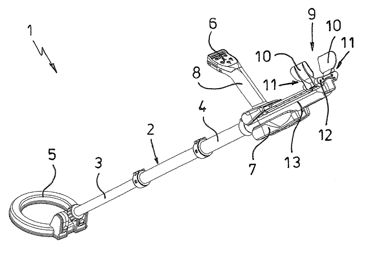
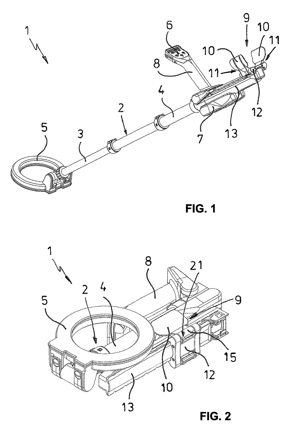
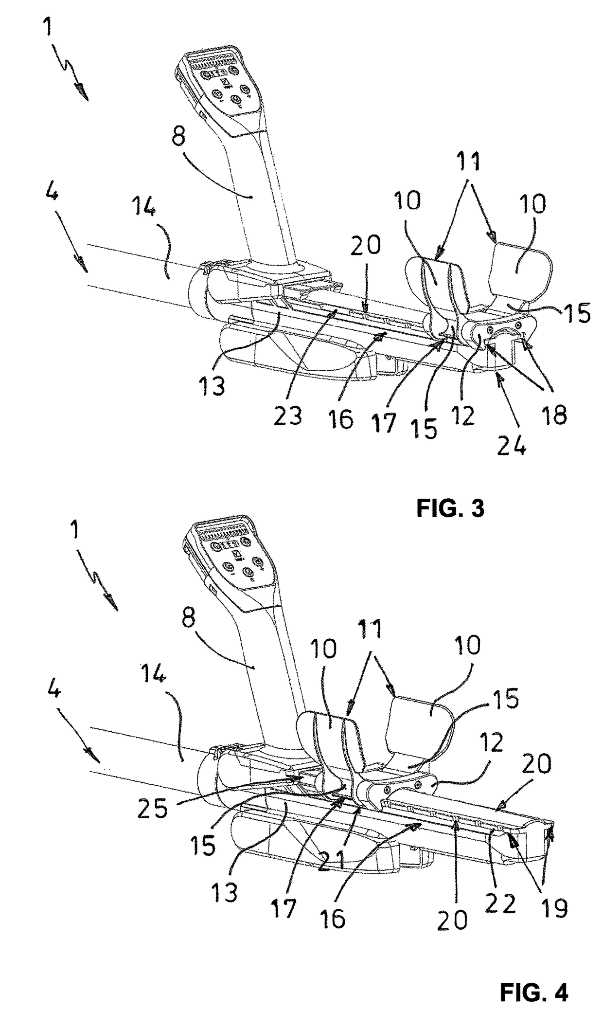
[0027]FIG. 1 illustrates an embodiment of a detector 1 according to the invention in an operating position. The detector includes a telescoping support tube 2 with at least one forward tube element 3 and a rear tube element 4, wherein a measuring probe 5 is pivotably attached in front at the forward tube element 3 and an electronic units 6, a battery compartment 7, a handle element 8 are arranged at the rear tube element 4 and axially offset therefrom in rear direction a U-shaped arm shell 9 with two arm support bars 10 is arranged. Thus the arm shell 9 is supported axially moveable relative to the handle element 8 and includes 2 arm shell elements 11 which are pivotably arranged laterally at a support slide 12 wherein the pivoting has performed in a transversal direction of the support tube 2. The support slide 12 is supported axially moveable by a support rail 13 extending in longitudinal direction of the support tube 2 wherein the support rail is attached at a rear tube end 14 of...


PUM


Abstract

A detector with a telescoping support tube wherein a measuring probe is arranged at a front of a forward tube element and an electronics unit with a battery compartment, a handle element and axially offset rearward therefrom a U-shaped arm shell with two arm support bars are arranged at a rear tube element, wherein the arm support bars are pivotable relative to the rear tube element. The arm shell is axially moveable relative to the handle element and includes two arm shell elements which are laterally arranged at a support slide and pivotably moveable in a transversal direction of the support tube. The support slide is supported axially moveable by a support rail. According to the invention it is provided that the support slide is fixateable in a disengageable manner at the support rail at various locations through the arm shell elements.

Description

RELATED APPLICATIONS[0001]This application claims priority from and incorporates by reference European Patent application EP 14 189 899.9 filed on Oct. 22, 2014.FIELD OF THE INVENTION[0002]The invention relates to a detector.BACKGROUND OF THE INVENTION[0003]A detector of this general type is known for example from U.S. Pat. No. D652,330 S. In this detector the support rail is configured as a circular rod which is supported by two clamps which are arranged at a battery compartment that is pivotably connected with the rear tube end of the rear tube element. The support rail extends over an entire length of the battery compartment. The support rail is divided by one of the clamps into a forward rail section and a rear rail section. The rear rail section oriented away from the support tube supports the support slide with the arm shell. Another support slide is arranged at the forward rail section oriented towards the support tube, wherein the other support slide supports the handle elem...

Claims


Application Information

Patent Timeline
Patent Type & Authority Patents(United States)
IPC IPC(8): G01V3/15F41H11/136
CPCF41H11/136G01V3/15
Inventor ANDEL, BENJAMIN
Owner VALLON 72800 ENINGEN DE
Why Eureka
Try Eureka