Method and device for dynamic monitoring of gas sensors

a gas sensor and dynamic monitoring technology, applied in the direction of electric control, instruments, machines/engines, etc., can solve the problems of incorrect evaluation of non-functional exhaust emission control systems, inability to accurately control the air/fuel ratio, and inability to accurately evaluate the effect of correct operation of exhaust emission control systems

Active Publication Date: 2014-12-04
ROBERT BOSCH GMBH
View PDF0 Cites 19 Cited by
  • Summary
  • Abstract
  • Description
  • Claims
  • Application Information

AI Technical Summary

Benefits of technology

[0036]A further advantage is obtained by expanding the method to include operating-point-dependent identification. Here provision is made that after each adaptation step, the adapted parameters are programmed into operating-point-dependent characteristic curves or multi-dimensional characteristics diagrams. This is made possible by recursive optimization that supplies re-adapted parameter sets for each adaptation step.

Problems solved by technology

If the dynamics of the upstream gas probe decrease, for example due to contamination or aging, the air / fuel ratio can then no longer be regulated with the necessary precision, so that the conversion performance of the exhaust emission control system declines.
Deviations can also occur in the diagnosis of the exhaust emission control system, and can cause an exhaust emission control system that is in fact operating correctly to be wrongly evaluated as non-functional.
If the sensor signal has not reached a specific intermediate value after a maximum time, this is interpreted as a dead-time fault.
It contains an excitation by way of a test injection, which increases not only fuel consumption but also emissions.
These methods take into account only symmetrical dead times and time constants, however.
The influence of gain also remains unaccounted for, so that a gain error influences the identification of the time constants.

Method used


Image

  • Method and device for dynamic monitoring of gas sensors
  • Method and device for dynamic monitoring of gas sensors

Examples


Embodiment Construction

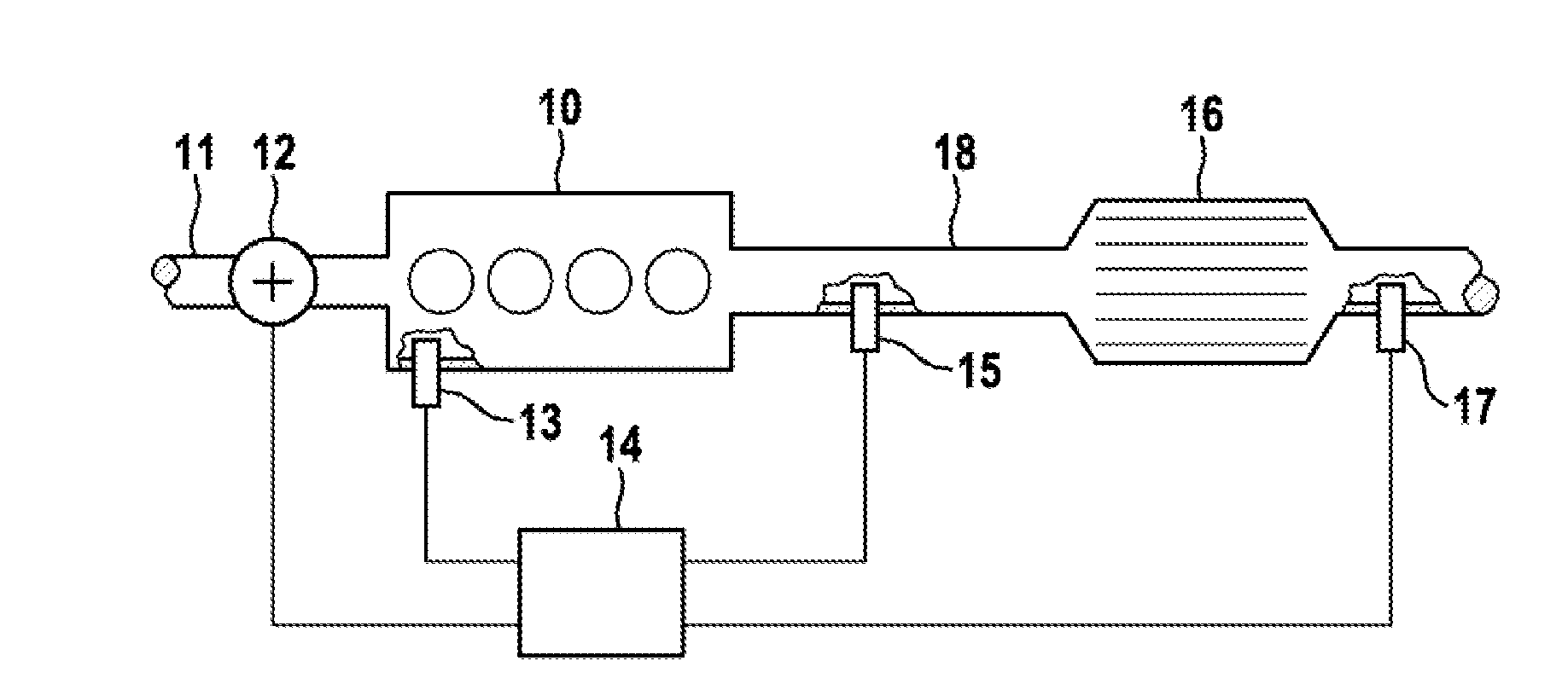
[0045]FIG. 1 schematically shows, using the example of an Otto-cycle engine, the technical environment in which the method according to the present invention for diagnosis of an exhaust gas probe 15 can be used. Air is delivered via an air intake 11 to an internal combustion engine 10, and its mass is identified using an air mass sensor 12. Air mass sensor 12 can be embodied as a hot film air mass sensor. The exhaust gas of internal combustion engine 10 is discharged through an exhaust gas duct 18, an exhaust emission control system 16 being provided behind internal combustion engine 10 in the flow direction of the exhaust gas. Exhaust emission control system 16 usually encompasses at least one catalytic converter.

[0046]An engine control system 14 is provided in order to control internal combustion engine 10, which system on the one hand delivers fuel to internal combustion engine 10 via a fuel metering system 13 and on the other hand has delivered to it the signals of air mass sens...


PUM


Abstract

In a method for monitoring the dynamics of gas sensors of an internal combustion engine, which gas sensors exhibit a low-pass behavior as a function of geometry, measurement principle, aging, or contamination, a dynamics diagnosis is carried out, upon a change in the gas state variable to be measured, on the basis of a comparison between a modeled and a measured signal. The parameters of the low-pass behavior are determined in direction-dependent fashion by minimizing direction-dependent error signals created by high-pass filtering and logical combination with direction-dependent saturation characteristic curves, the direction-dependent error signals being calculated by comparing the modeled and the measured signal for a rising and a falling signal component.

Description

BACKGROUND OF THE INVENTION[0001]1. Field of the Invention[0002]The present invention relates to a method and an apparatus for monitoring the dynamics of gas sensors of an internal combustion engine which are disposed, for example, as gas probes in the exhaust gas duct of an internal combustion engine as part of an exhaust gas monitoring and abatement system or as gas concentration sensors in an intake air passage of the internal combustion engine, the gas sensor exhibiting a low-pass behavior as a function of geometry, measurement principle, aging, or contamination, a dynamics diagnosis being carried out, upon a change in the gas state variable to be measured, on the basis of a comparison between a modeled and a measured signal, and the measured signal being an actual value of an output signal of the gas sensor and the modeled signal being a model value.[0003]2. Description of the Related Art[0004]In order to reduce emissions in passenger cars having Otto-cycle engines it is usual ...

Claims


Application Information

Patent Timeline
Patent Type & Authority Applications(United States)
IPC IPC(8): G07C5/08
CPCG07C5/0808F02D41/1456F02D41/1458F02D41/1495F02D2041/1423F02D2041/1431F02D2041/1432F02D2041/1433
Inventor ZIMMERSCHIED, RALF
Owner ROBERT BOSCH GMBH
Why Eureka
Try Eureka