Brake disk for a disk brake

a technology of brake disc and brake disc, which is applied in the direction of mechanical equipment, couplings, transportation and packaging, etc., can solve the problems of increased wear, premature fatigue, and the screw may lose the parallel position of the disc brake axis, so as to protect the disc from bending stress and simplify the assembly of the brake disc

Inactive Publication Date: 2004-10-26
SAB WABCO BSI VERKEHRSTECHN PRODS
View PDF12 Cites 19 Cited by
  • Summary
  • Abstract
  • Description
  • Claims
  • Application Information

AI Technical Summary

Benefits of technology

According to a first embodiment form of the retaining elements according to the invention these may be designed as a radially outwardly extending retaining lug or as a circumferential retaining flange on the hub body. The formation of the retaining element as a retaining lug on the hub body has the advantage that between two such lugs there remains a free space through which cooling air may flow during operation. Furthermore on assembly of the brake disc, in a simple manner a likewise lug-shaped designed brake ring flange may be introduced through the free space into the intermediate space between the hub flange and the retaining elements. The integral formation of the retaining element with the hub body simplifies the assembly of the brake disc since the retaining elements do not need to be assembled separately.
In a further formation of the last mentioned embodiment form the retaining element formed on the hub body may comprise an axially parallel opening with a sleeve arranged therein, wherein the opening in the retaining element is arranged aligned to the corresponding opening in the hub flange. A screw passing through the hub flange and the braking ring flange may be led through the sleeve, wherein the sleeve is then supported on one side on the braking ring flange. The sleeve serves for pretensioning the brake ring against the hub flange. This is effected via the support of the sleeve on the brake ring flange, wherein on the opposite end of the sleeve the screw engages on the screw thread via the screw head or the nut. By way of the mounting in the sleeve the screw at the same time is additionally protected from bending stresses. By way of the fact that the sleeve is arranged in the opening of the retaining element, furthermore an indirect radial fixing of the screw end relative to the hub body is achieved. At the same time the sleeve however remains axially parallel displaceable in the opening of the retaining element, so that it may transmit the desired axial pretension force onto the brake ring flange.
According to a second design form of the retaining element of the present invention, this is formed as an L-shaped retaining bracket which in a first limb comprises an opening for leading through the end of the screw. Furthermore on the hub body there is provided an axially orientated groove in which the second limb of the mentioned retaining bracket may be arranged. The orientation of the groove is defined as the direction from the base of the groove towards its opening, that is to say parallel to the walls of the groove. Of course this embodiment form of the retaining elements may also be combined with the above explained form since the individual retaining elements distributed along the circumference of the hub body are basically independent of one another. The L-shaped retaining bracket is mounted in the axially orientated groove on the hub body in a manner such that it remains movable in the axial direction and is fixed in the radial direction as well as preferably also in the circumferential direction. As a whole then the desired radial fastening of the retaining bracket is achieved, wherein the retaining brackets however simultaneously with the tightening of the screws move axially and thus may transmit the set pretension force onto the brake ring flange. The use of retaining brackets has the advantage that on assembly of the disc brake these may firstly be removed so that the brake ring and disc body may be put together in an unhindered manner. Only on tightening the screws are the retaining brackets then attached after one another. Furthermore by way of the application of the variously dimensioned retaining brackets there may be effected a simple adaptation of the dimensions of the brake ring and hub body.
According to a further embodiment form it is envisaged for the screw to be designed such that firstly the head has a surface which by way of its bearing an a collar of the hub formed specially as a support, there is effected a rotational securement when screwing the nut on and off, and secondly below the head there is incorporated a knurling which on assembly of the screw into the hub digs into the receiver bore and by way of this firmly retains the screw with a press fit in the hub so that on assembly of the brake ring it does not need to be held in position by hand.

Problems solved by technology

However with such a design there exists the danger that with thermal expansions the screws may lose their parallel position to the axis of the disc brake.
This leads to considerable bending stresses of the screws which may lead to an increased wear, premature fatigue and in the worst case to a failure of the screws.
This embodiment form however is very complicated and thus expensive and with thermal expansions leads to undesired changes in the pretension of the screws.
It is however disadvantageous that additional means for torque transmission mentioned type to mount the screw heads as well as nuts in spherical bearing shells, by which means the screws may be pivoted out of their axially parallel bearings essentially without bending and shear stresses.
This embodiment form however is very complicated and thus expensive and with thermal expansions leads to undesired changes in the pretension of the screws.
It is however disadvantageous that additional means for torque transmission must be provided between the hub body and the tension ring so that no bending stresses of the screws occur perpendicular to the radial direction.
On account of these means the constructional effort is increased and the assembly is made more difficult.
With disc brakes ventilated at the inside, the tension ring may considerably handicap the supply of cooling air to the brake disc.
Furthermore there also exists the possibility that with thermal expansion, the forces on the tension ring occur assymetrically with respect to the rotational axis of the disc brake and that on account of this the undesired bending stresses indeed do arise.

Method used


Image

  • Brake disk for a disk brake
  • Brake disk for a disk brake
  • Brake disk for a disk brake

Examples


Embodiment Construction

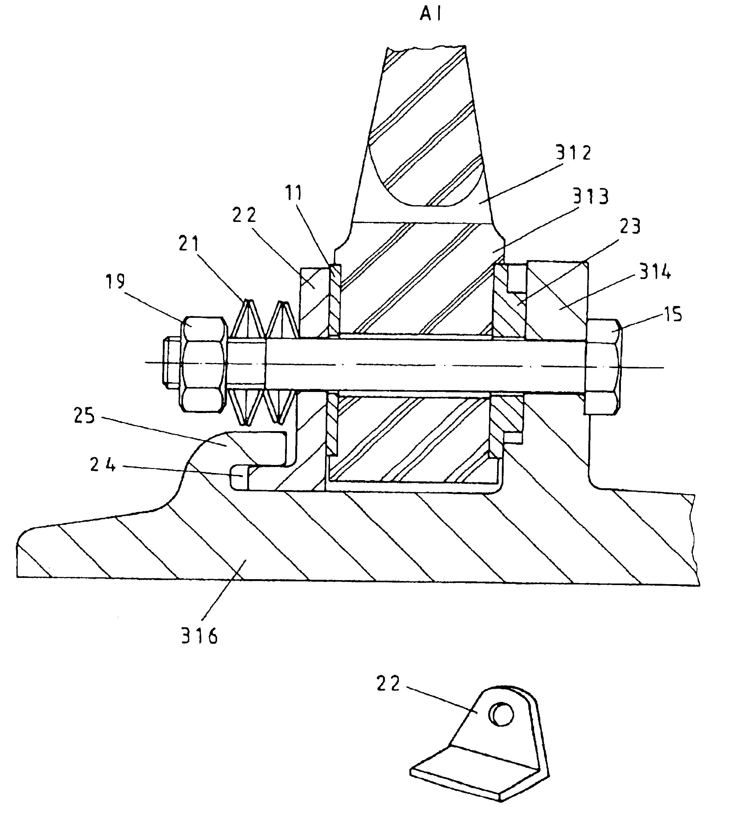
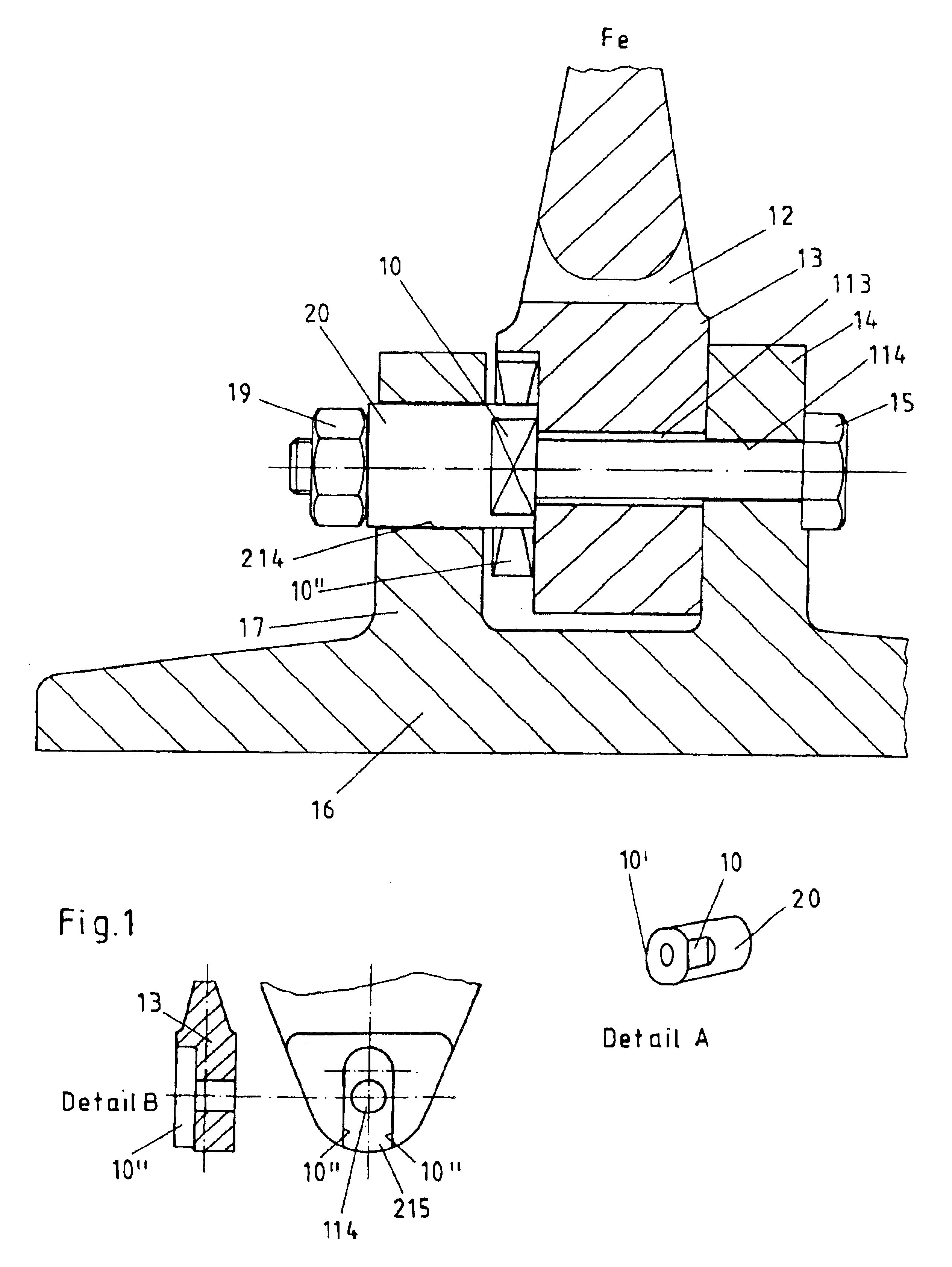
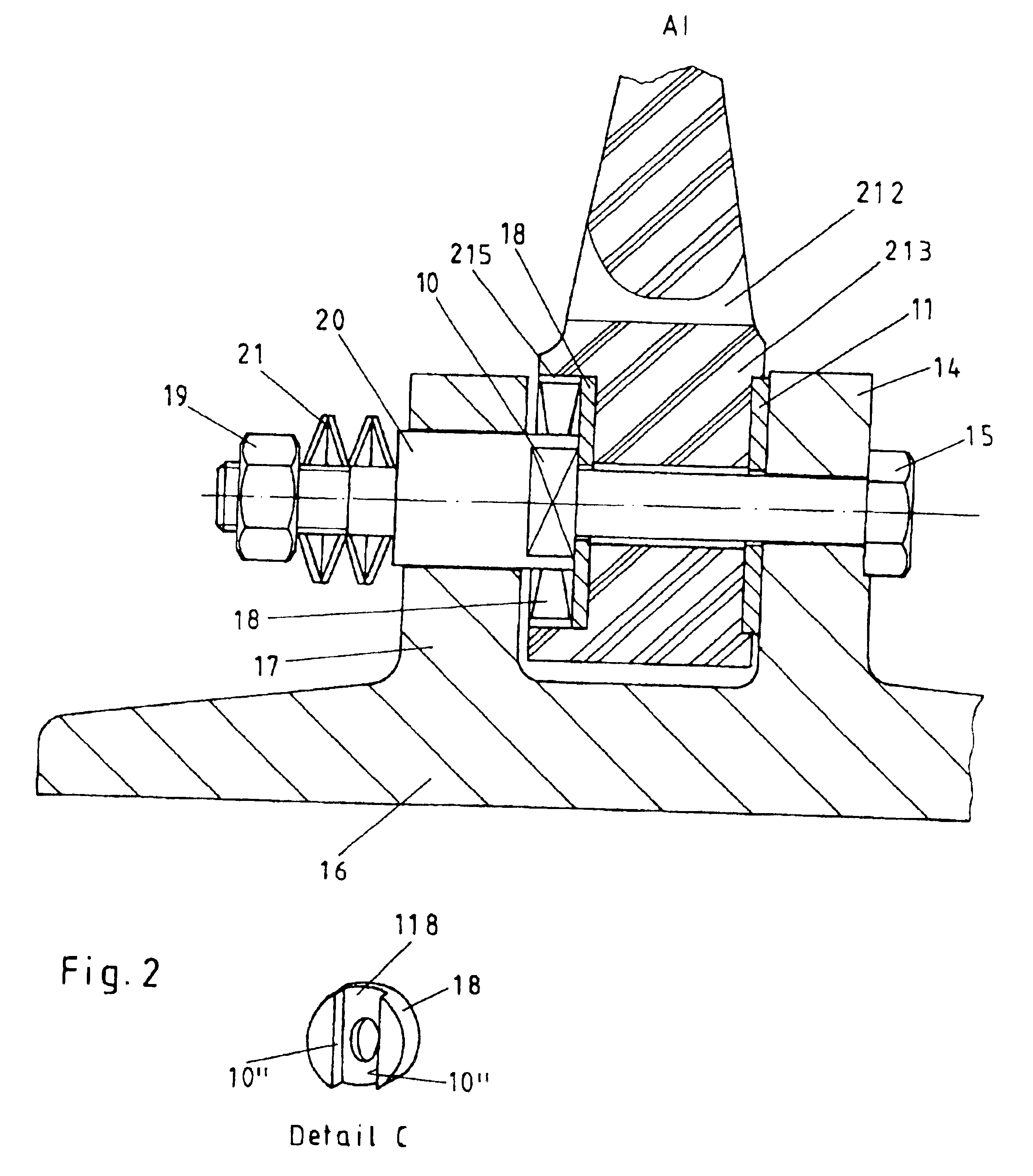
In FIG. 1 there is shown a cross section through the screw connection between the hub body 16 and the brake ring 12. The hub body 16 is arranged on the shaft of the axle of a rail vehicle (not shown) in a rotationally fixed manner and is connected to the brake ring 12 in a rotationally fixed manner. The brake ring 12 on one or on two sides comprises friction surfaces (not shown) on which brake shoes may engage for producing the braking force. Since with the braking procedure there occurs the production of heat at the brake ring 1, the connection between the brake ring 12 and the hub body 16 must be designed such that a thermal expansion of the brake ring 12 may be effected and simultaneously a secure and centred seating of the brake ring relative to the hub body 16 or to the rotational axis of the brake disc is ensured. Simultaneously it is desirable for the screws 15 used for connection of the hub body 16 to the brake ring 12 to be protected from bending stresses in the case of the...


PUM


Abstract

The invention relates to a brake disc for a rail vehicle, with which a hub body (16) and a brake ring (12) are connected to one another such that with braking procedures a thermal expansion of the brake ring (12) relative to the hub body (16) is possible. At the same time screws (15) pass through axially aligned openings in a hub flange (14) arranged on the hub body (16) and a brake ring flange (13) arranged on the brake ring (12). According to the invention the screws at their end exiting the brake ring flange (13), by way of a retaining element which, for example, may be a retaining lug (17) formed integrally on the hub body (16) or a retaining bracket fixed on the hub body, may be fixed relative to the hub body (16) so that an axially parallel position of the screws (15) and a centering of the brake ring (12) is ensured even with thermal expansions. The mounting of the screws (15) is effected indirectly via an axially displaceably movable sleeve (20) or by a retaining braket engaging into a groove on the hub. Furthermore there are provided radial guides for the brake ring (12) which may be realised, for example, by the guiding of the sleeve (20) in a slide block.

Description

The invention relates to a brake disc for a disc brake, in particular for rail vehicles. This contains a hub body with a radially outwardly extending hub flange with axially parallel openings in which screws may be arranged in order to connect a brake ring flange of a brake ring to the hub body, said brake ring flange being arranged radially overlapping and axially adjacent the hub body. It further relates to a brake ring for a disc brake, in particular for rail vehicles containing a radially extending brake ring flange with axially parallel openings in which screws may be arranged in order to connect a hub flange of a hub body to the brake ring, said hub flange being arranged radially overlapping and axially adjacent the brake ring flange.STATE OF THE ARTDisc brakes of the above mentioned type are for example known from DE 26 20 623 A1 (FIGS. 1 and 2). They consist of a hub body which is arranged in a rotationally fixed manner on the shaft of the axle of a vehicle, as well as a bra...

Claims


Application Information

Patent Timeline
Patent Type & Authority Patents(United States)
IPC IPC(8): F16D65/12
CPCF16D65/12F16D2065/1392F16D2065/136F16D2065/1316
Inventor LEHMANN, WOLFGANGGRONEMANN, MANFREDRUPPERT, HELMUTWATSON, JOHN
Owner SAB WABCO BSI VERKEHRSTECHN PRODS
Why Eureka
Try Eureka