Display card with user interface

a technology of user interface and display card, which is applied in the direction of coded identity card or credit card actuation, data processing application, instruments, etc., can solve the problems of inability to ensure, difficult to provide a secure device, and high replacement cost, and achieve the effect of great improvement of functionality

Active Publication Date: 2018-01-09
MASTERCARD INT INC
View PDF13 Cites 17 Cited by
  • Summary
  • Abstract
  • Description
  • Claims
  • Application Information

AI Technical Summary

Benefits of technology

[0020]Advantageously, the communication between the chip and the micro-terminal allows greatly improved functionality over known cards since the micro-terminal is able to obtain information from within the Chip.

Problems solved by technology

However, a problem with using mobile telephones for applications such as payment devices is that it is difficult to provide a secure device.
Mobile telephones are required to support a diverse range of applications and it cannot be ensured that these are all from trusted sources.
In addition, the relatively large cost of a mobile telephone means that if it is lost, as sometimes happens with items in common usage, then it is expensive to replace.
Moreover, DCKs are easily used for both contact and contactless information transfer with a terminal whereas mobile telephones are only usable for contactless information transfer.
There is no communication path on the DCK between the Chip and the Display Control and accordingly these modules are not able communicate with each other.
This requires the Display Control to be implemented as a tamper resistant / tamper detective-responsive component and therefore increases costs.
Another problem with the architecture of the DCK shown in FIG. 1 is that the Display Control can only provide services that do not require access to the applications in the Chip.
It therefore cannot provide services such as the reading of an accumulator / counter of the balance of a payment application, or the reading of a trace record in a log file.
However, a problem with the architecture of FIG. 2 is that the additional services provided are limited to what can be achieved by reading the communication between the contact and contactless interfaces and the Chip.
It is not possible for the Display Control to directly access any of the information in the Chip.
Moreover, the architectures of the DCKs in FIGS. 1 and 2 are not scalable.
A further problem with known DCKs is that their operation is restricted by the technique of powering the Chip.

Method used


Image

  • Display card with user interface
  • Display card with user interface
  • Display card with user interface

Examples


Embodiment Construction

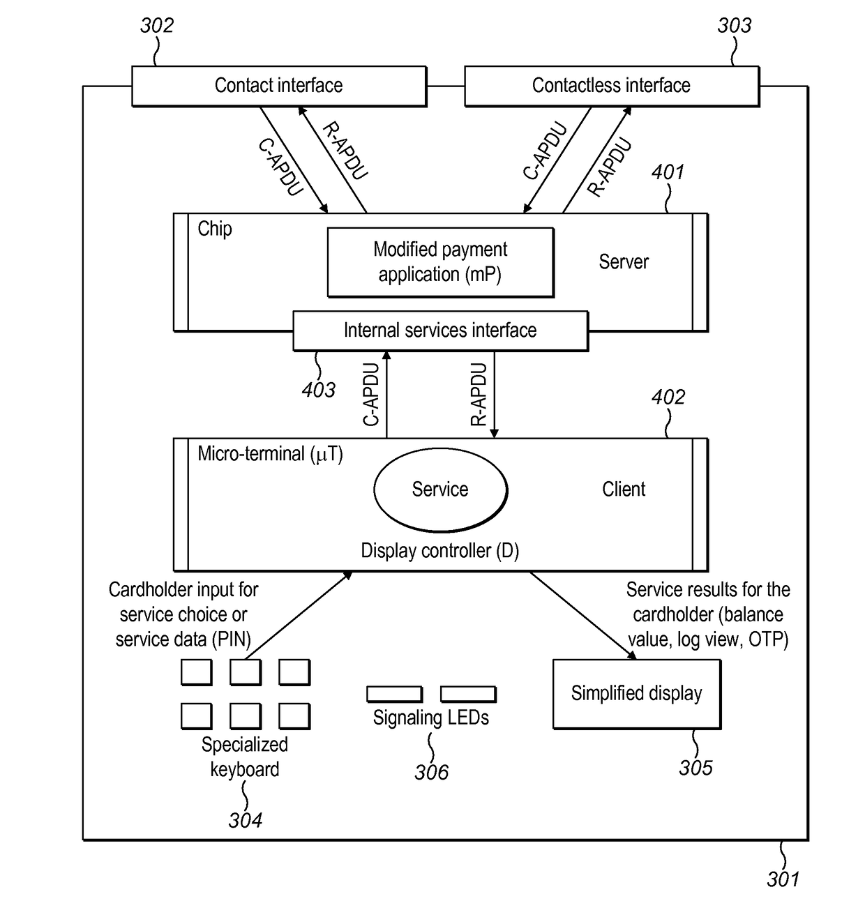
[0044]Embodiments of the invention improve the functionality of a DCK through the use of a new architecture. The new architecture allows an increased range of services to be provided by the DCK.

[0045]In a particularly preferred embodiment, a DCK is used as a payment card. Services provided by DCKs used as payment cards according to embodiments include one or more of:[0046]On-device Cardholder Verification Method, CVM—this service allows the keyboard of the card to be used to input an on device CVM, i.e. m-PIN (similar to that verified by a mobile phone), before being presented to a POI terminal.[0047]On-card account selection—this service allows the pre-selection of an application, such as an EMV application, from several, which gives a Cardholder the ability to select between a debit or a credit payment product, or to use “loyalty points” as private currency to pay at the POI terminal, etc.[0048]On-card activation of the contactless payment functionality—this service allows the Car...


PUM


Abstract

A display card 301 with a user interface for providing one or more services. The card 301 comprises: an external interface 302, 303 for communication with a terminal external from the card 301; a Chip 401 comprising one or more servers for storing one or more applications, wherein the Chip 401 is arranged to communicate with the external interface 302, 303; a user interface 304, 305, 306 for interacting with a user of the card 301; a micro-terminal 402 for controlling the provision of one or more services, wherein the micro-terminal 402 is arranged to communicate with the user interface 304, 305, 306; and the Chip 401 and micro-terminal 402 are arranged to communicate with each other via an internal interface 403 of the Chip 401. Applications include payment cards and passes.

Description

CROSS-REFERENCE TO RELATED APPLICATION[0001]This application is a U.S. National Stage filing under 35 U.S.C. §119, based on and claiming benefit of and priority to GB Patent Application No. 1310774.3 filed Jun. 17, 2013, the entire contents of which are hereby incorporated in their entirety for all purposes.FIELD OF THE INVENTION[0002]The field of the present invention is chip cards with user interfaces. The user interfaces may include one or more of a display, a keyboard, signalling LEDs, and biometric sensors. In particular, embodiments provide a new display card with keyboard (DCK) architecture that has improved functionality over known DCK architectures.BACKGROUND OF THE INVENTION[0003]The use of passive cards, comprising a magnetic strip and / or chip for storing information, for applications such as payment devices (i.e. chip and PIN) and travel passes, is well known. Advantages of using such cards include the cards being cheap and easy to manufacture. In addition, their small s...

Claims


Application Information

Patent Timeline
Patent Type & Authority Patents(United States)
IPC IPC(8): G06K19/06G06K19/073G07F7/08G06Q20/34G06K19/077
CPCG06K19/07701G06K19/073G06K19/07705G07F7/0806G06K19/07709G06Q20/3574G06K19/07707G07F7/0853G07F7/1008
Inventor RADU, CRISTIANPOCHIC, SEBASTIENATES, FIKRET
Owner MASTERCARD INT INC
Why Eureka
Try Eureka