Wireless power transmission system
a power transmission system and wireless technology, applied in the field of wireless power transmission systems, can solve the problem of small resistance component relative to reactance component, and achieve the effect of reducing the potential variation of reference potential in the power reception apparatus
- Summary
- Abstract
- Description
- Claims
- Application Information
AI Technical Summary
Benefits of technology
Problems solved by technology
Method used
Image
Examples
first embodiment
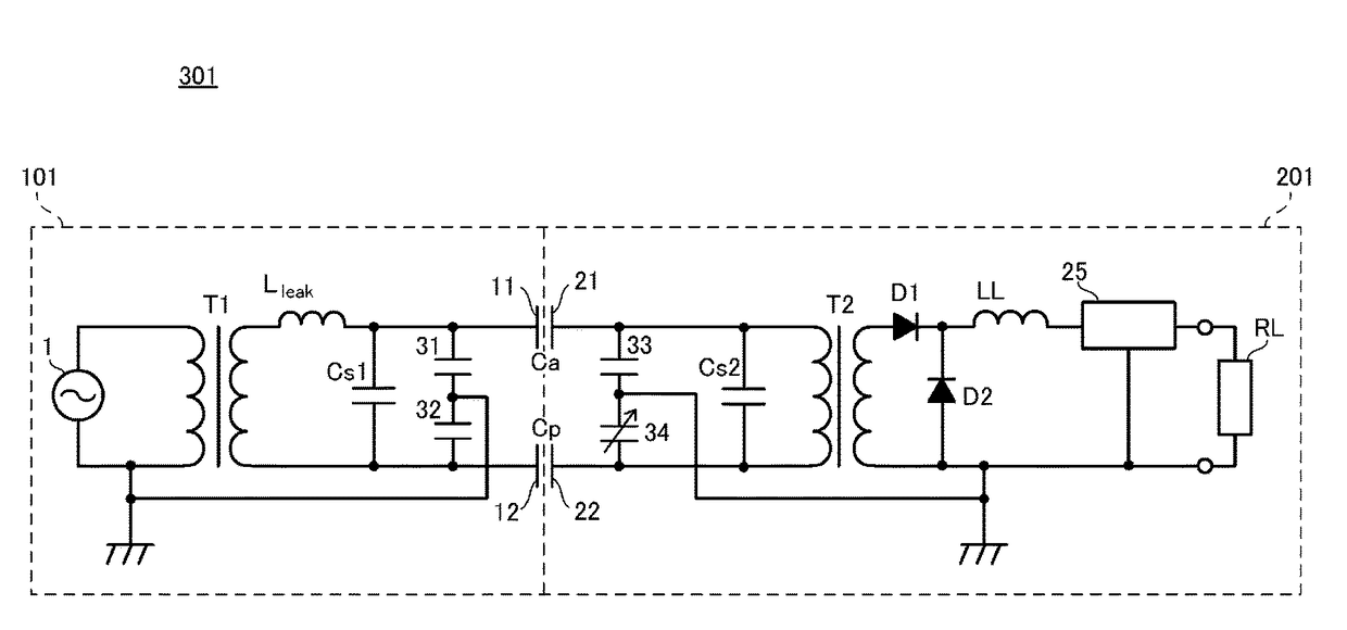
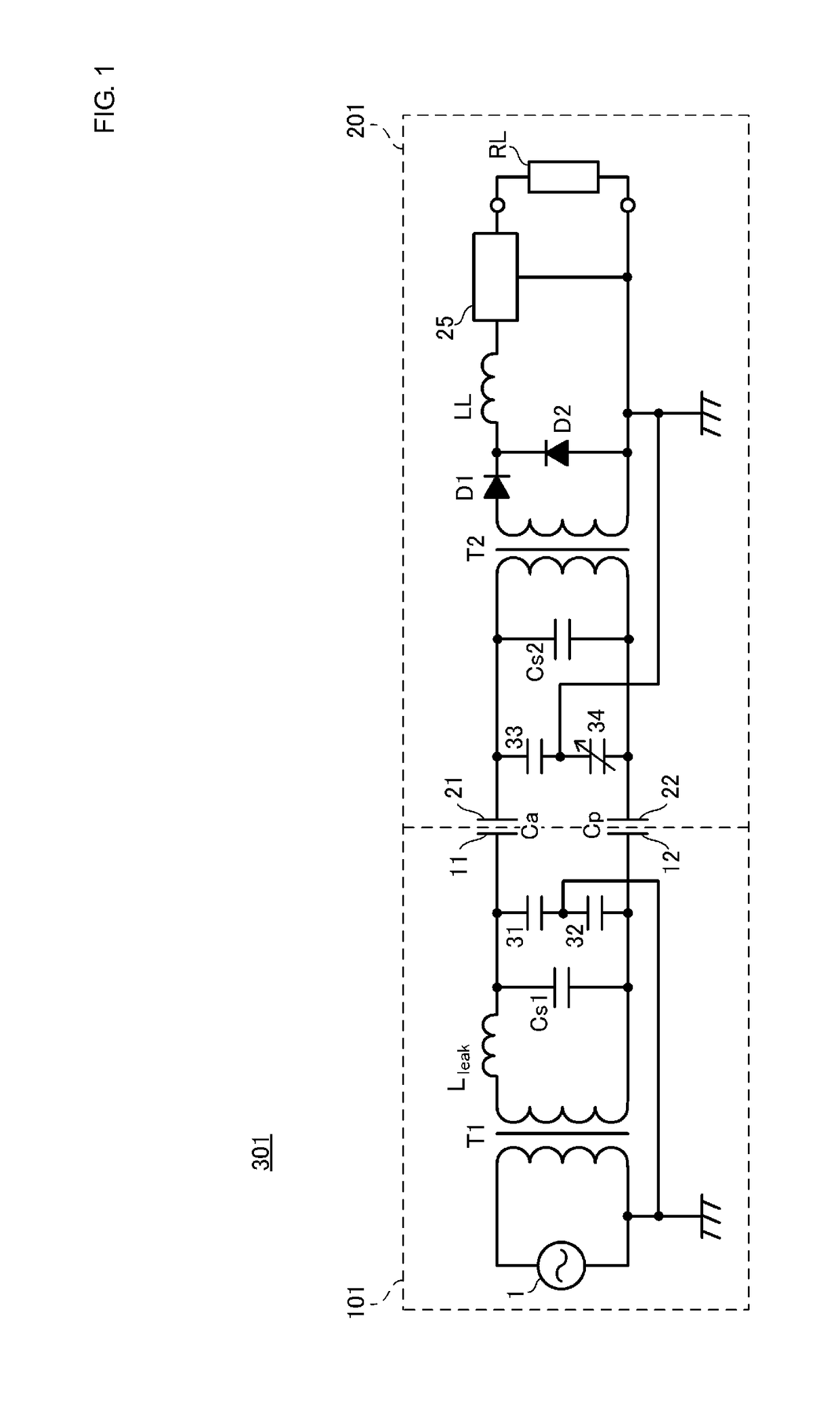
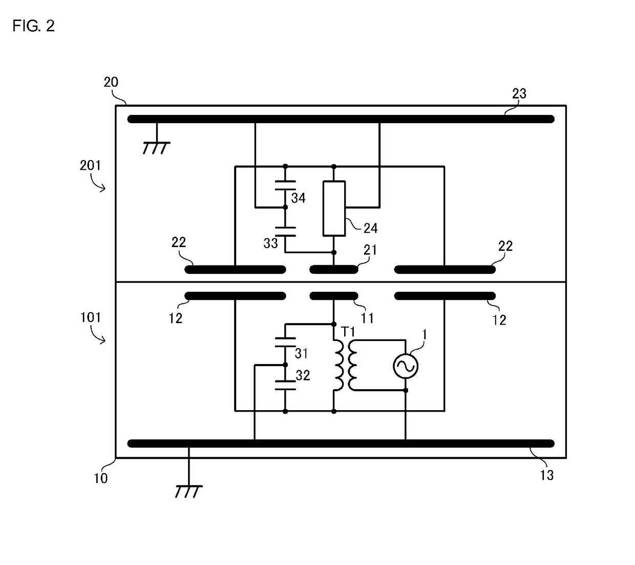
[0029]FIG. 1 is a circuit diagram of a wireless power transmission system 301 according to a first embodiment. The wireless power transmission system 301 includes a power transmission apparatus 101 and a power reception apparatus 201. The power reception apparatus 201 includes a load circuit RL. The load circuit RL includes a secondary battery, a charging circuit for the secondary battery, a touch panel, which serves as an input unit, and so on, and none of them are illustrated. The power reception apparatus 201 is, for example, a portable electronic apparatus. Examples of the portable electronic apparatus include a cellular phone, a PDA, a portable music player, a laptop computer, and a digital camera. The power reception apparatus 201 is placed on the power transmission apparatus 101, and the power transmission apparatus 101 charges the secondary battery of the power reception apparatus 201.
[0030]The touch panel operates on the secondary battery serving as a power source.
[0031]Ref...
second embodiment
[0082]A wireless power transmission system according to a second embodiment differs from the wireless power transmission system according to the first embodiment in terms of a power reception apparatus. Hereinafter, the differences will be described.
[0083]FIG. 9 is an equivalent circuit diagram of a wireless power transmission system 302 according to the second embodiment. The wireless power transmission system 302 includes a power transmission apparatus 102 and a power reception apparatus 202. The power transmission apparatus 102 is identical to the power transmission apparatus 101 according to the first embodiment, and thus description thereof will be omitted.
[0084]In the power reception apparatus 202, inductors 35 and 36 connected in series between the active electrode 21 and the passive electrode 22 are provided. Specifically, the inductor 35 is connected to the active electrode 21, and the inductor 36 is connected to the passive electrode 22. A node between the inductors 35 and...
third embodiment
[0088]In a wireless power transmission system according to the present embodiment, capacitances corresponding to the capacitors 31, 32, 33, and 34 described in the first embodiment are formed by parasitic capacitances produced in a power transmission apparatus and a power reception apparatus, and the reference potential of the power reception apparatus is stabilized. Hereinafter, the differences will be described.
[0089]FIG. 10 is a sectional view conceptually illustrating primary portions of a power transmission apparatus 103 and a power reception apparatus 203 that constitute a wireless power transmission system 303 according to a third embodiment. FIG. 11 is a circuit diagram of the wireless power transmission system 303 illustrated in FIG. 10. It is to be noted that the capacitors Cs1 and Cs2 are omitted in FIG. 11.
[0090]In the wireless power transmission system 303, the power transmission apparatus 103 and the power reception apparatus 203 include shield electrodes 13A and 23A, ...
PUM
 Abstract
Description
Claims
Application Information
 - R&D
- Intellectual Property
- Life Sciences
- Materials
- Tech Scout
- Unparalleled Data Quality
- Higher Quality Content
- 60% Fewer Hallucinations
Browse by: Latest US Patents, China's latest patents, Technical Efficacy Thesaurus, Application Domain, Technology Topic, Popular Technical Reports.
© 2025 PatSnap. All rights reserved.Legal|Privacy policy|Modern Slavery Act Transparency Statement|Sitemap|About US| Contact US: help@patsnap.com


