Centrifuge vessel assembly

a technology for centrifuges and vessels, applied in centrifuges, laboratory glassware, chemistry apparatus and processes, etc., can solve the problems of high acceleration force limits, time-consuming centrifugation process, and more difficult cleaning, so as to achieve large capacity and reduce yield loss

Active Publication Date: 2018-01-16
THERMO ELECTRONICS LED GMBH
View PDF18 Cites 2 Cited by
  • Summary
  • Abstract
  • Description
  • Claims
  • Application Information

AI Technical Summary

Benefits of technology

[0005]It is an object of the present invention to provide a centrifuge vessel which is capable of withstanding high acceleration values during centrifugation and at the same time has a large capacity without giving rise to cleaning problems and losses of yield.
[0008]Thus the cross-sectional area of the centrifuge vessel is not rotationally symmetrical, as in the prior art, and as has hitherto been avoided, since high forces occur during centrifugation which might destroy the centrifuge vessel. These forces can be kept under control when use is made of the centrifuge vessel assembly of the present invention. On account of its shape, lower forces are set free in the centrifuge vessel than is the case in a centrifuge vessel of comparable capacity but having a greater vessel height. The centrifuge vessel used in the centrifuge vessel assembly of the present invention has the advantage of making it possible to provide a vessel having a high volumetric capacity accompanied by a low overall vessel height. In this way, the prior centrifuges can still be used, since the previous overall vessel height remains unchanged. Furthermore, the centrifuge vessel of the present invention is easy to wash, since it has no corners in its bottom region, and is thus quickly reusable. Furthermore, the centrifuge vessel has no corners at the side walls or in a bottle neck, as might influence the separating results.
[0010]Provision may be made for the centrifuge vessel to have a bottom surface displaying the oval cross-sectional area. This has the advantage that the centrifuge vessel will be easy to clean and that no sample residues will remain in the interior of the centrifuge vessel.
[0011]In one exemplary embodiment of the centrifuge vessel of the present invention, provision may be made for a middle region of the centrifuge vessel to display the oval cross-sectional area. For this purpose, provision may additionally be made for the centrifuge vessel to have a side wall of a specific height, wherein the oval cross-sectional area remains constant over the entire height, that is to say, does not change over this entire vertical region. In this way, the centrifuge vessel will be easy to clean, since all corners have been obviated in this region. For example, the side wall is disposed in a middle region of the centrifuge vessel.
[0014]For practical purposes, provision may be made for the centrifuge vessel to have a capacity of from approximately 750 milliliters to approximately 1000 milliliters. Compared with conventional centrifuge vessels, this represents an increase in capacity, which is made possible by the oval design of at least one cross-sectional area in the interior of the centrifuge vessel. By this means, the vessel height of the centrifuge vessel can remain unchanged when compared with conventional centrifuge vessels. Advantageous increases in capacity are thus obtained. The capacity of an oval vessel is, for example, equal to a gain of approximately one third over the capacity of a round bottle of identical overall vessel height. This means that in these embodiments the previous overall vessel height is retained, while the centrifuge vessels of the present invention have an enhanced capacity.
[0016]The adapter holding the centrifuge vessel preferably also has an oval cross-section and is made to follow the outer contour of the centrifuge vessel such as to support its outer surface at least in the region of its side walls. The adapter may consist of an elastic material, such as an elastomeric plastics material, which can adapt to the form of the centrifuge vessel and the holding means and can absorb at least some of the centrifugal forces and thus reduce their impact on the centrifuge vessel.

Problems solved by technology

A centrifuging process is to a certain extent time consuming.
However, limits are set on account of the high acceleration forces that occur during centrifugation.
Such centrifuge vessels have a greater capacity due to their corners, but they are more difficult to clean.
This is a drawback, since the centrifuge vessels will often be used a number of times to save on costs.
However, the cost should not be enhanced by an increased effort required for cleaning.
Another disadvantage of such square type centrifuge vessels is the fact that after centrifugation residues of the sample remain in the corners and the yield of the sample is thus diminished.

Method used


Image

  • Centrifuge vessel assembly
  • Centrifuge vessel assembly
  • Centrifuge vessel assembly

Examples


Embodiment Construction

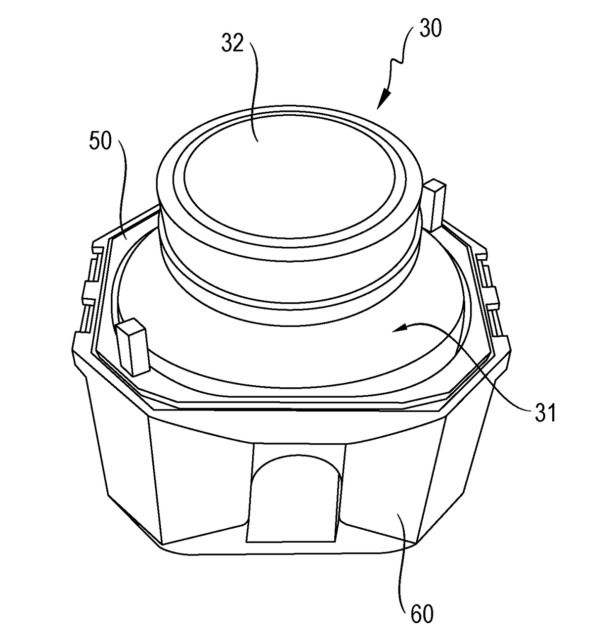
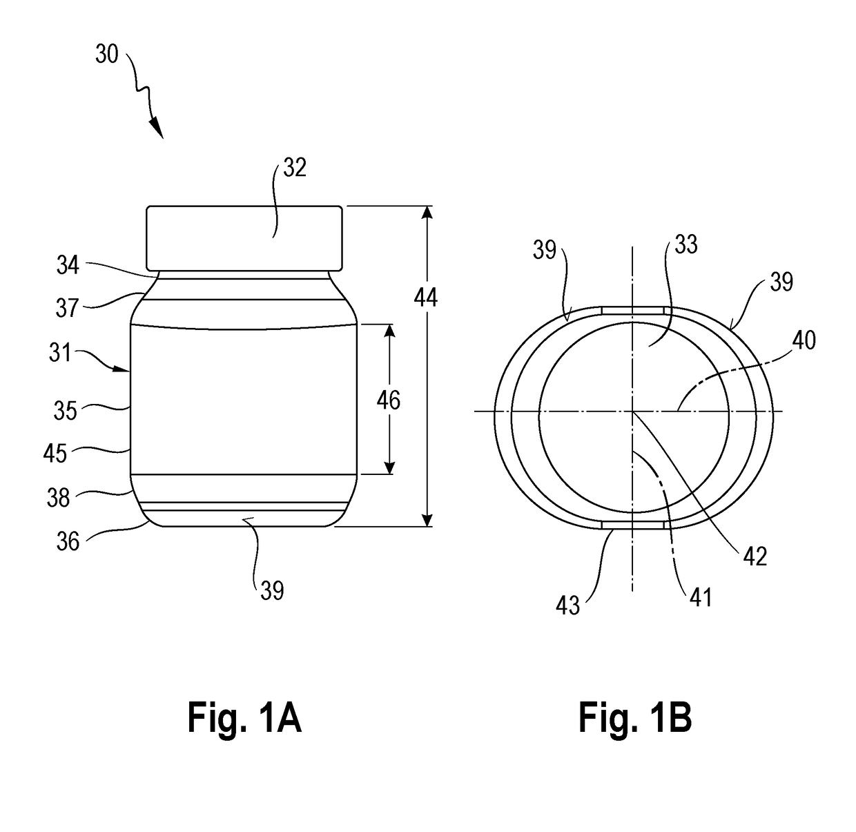
[0023]FIG. 1 shows a first exemplary embodiment of a centrifuge vessel 30 in two views, of which FIG. 1A is a side view of the centrifuge vessel 30 and FIG. 1B is a top view of the centrifuge vessel 30. The centrifuge vessel 30 comprises a vessel body 31 comprising an opening that can be sealed by means of a closure element 32 in the form of a screw-on lid. For this purpose, the lid 32 is of a circular cross-section, as shown in FIG. 1B.

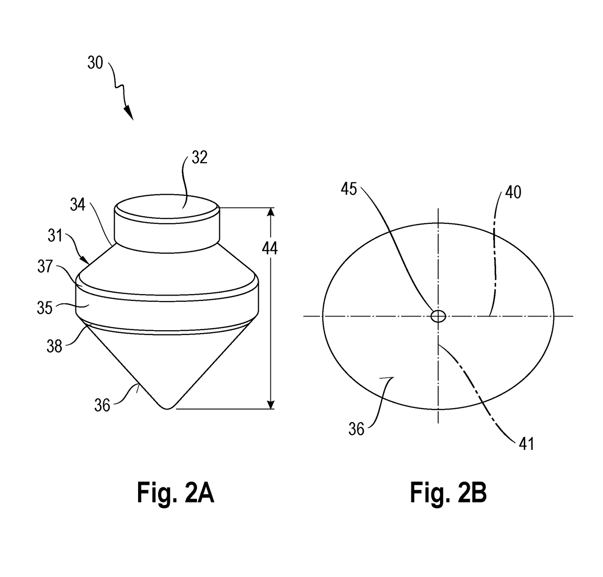
[0024]FIG. 1A shows the vessel body 31 comprising a top portion 34 located in the proximity of the opening, a middle portion 35, and a bottom portion 36. The top portion 34 merges continuously into the middle portion 35 by way of a first transition zone 37, and the middle portion 35 merges continuously into the bottom portion 36 by way of a second transition zone 38. The vessel body 31 has an oval cross-sectional area 39 in the top portion 34, in the middle portion 35, and in the bottom portion 36, and the bottom portion 36 has a smaller peripheral c...


PUM


Abstract

The present invention relates to a centrifuge vessel assembly for use in a centrifuge, comprising a centrifuge vessel for holding a sample to be centrifuged, an adapter holding the centrifuge vessel, and a holding means holding the adapter for attaching the centrifuge vessel assembly to a rotor of the centrifuge, said centrifuge vessel having a vessel body and a sealable opening through which the sample to be centrifuged can be filled into said vessel, said vessel body having a cross-sectional area and a vessel height, said vessel height being oriented at right angles to said cross-sectional area, wherein said cross-sectional area is in the form of an oval cross-sectional area.

Description

CROSS-REFERENCE TO RELATED APPLICATIONS[0001]The present application claims priority under 35 U.S.C. §119 of German Patent Application No. 10 2012 013 642.0, filed Jul. 9, 2012, the disclosure of which is hereby incorporated herein by reference in its entirety.FIELD OF THE INVENTION[0002]The present invention relates to a centrifuge vessel assembly for use in a centrifuge, comprising a centrifuge vessel for holding a sample to be centrifuged, an adapter holding the centrifuge vessel, and a holding means holding the adapter for attaching the centrifuge vessel assembly to a rotor of the centrifuge. The centrifuge vessel has a vessel body and a sealable opening through which the sample to be centrifuged can be filled into said vessel.BACKGROUND OF THE INVENTION[0003]Centrifuge vessels, sample containers, and centrifuge bottles are special containers comprising a vessel body and a closable opening for use in a centrifuge. In a centrifuge, liquid mixtures, for example, are separated by i...

Claims


Application Information

Patent Timeline
Patent Type & Authority Patents(United States)
IPC IPC(8): B04B1/00B04B7/08B01L3/00B04B5/04B01L9/06
CPCB04B7/08B01L3/5021B04B2005/0435B01L2300/0851B01L2300/123B01L9/06B04B7/12
Inventor BALLHAUSE, NORMAN
Owner THERMO ELECTRONICS LED GMBH
Why Eureka
Try Eureka