Eureka AIR delivers breakthrough ideas for toughest innovation challenges, trusted by R&D personnel around the world.

Fault current reduction structure of multi-level converter and apparatus using the fault current reduction structure

a multi-level converter and fault current reduction technology, applied in the direction of electrical equipment, power conversion systems, emergency protective circuit arrangements, etc., can solve problems such as power transmission lines and cables being damaged, and achieve the effect of reducing a fault curren

Inactive Publication Date: 2018-01-16
UNIV IND FOUND UIF
View PDF34 Cites 5 Cited by
  • Summary
  • Abstract
  • Description
  • Claims
  • Application Information

AI Technical Summary

Benefits of technology

[0026]According to the exemplary embodiments, it is possible to reduce a fault current in a multi-level converter by bypassing or blocking the fault current.
[0027]In addition, since a fault current can be reduced, it is possible to prevent damage to IGBTs, diodes and capacitors. Also, since the discharge of the voltage of each capacitor can be prevented, it is possible to quickly reboot a multi-level converter after the removal of a fault current.

Problems solved by technology

Also, power transmission lines and cables may be damaged by a fault current.

Method used


Image

  • Fault current reduction structure of multi-level converter and apparatus using the fault current reduction structure
  • Fault current reduction structure of multi-level converter and apparatus using the fault current reduction structure
  • Fault current reduction structure of multi-level converter and apparatus using the fault current reduction structure

Examples


Embodiment Construction

[0050]Advantages and features of the invention and methods of accomplishing the same may be understood more readily by reference to the following detailed description of embodiments and the accompanying drawings. The invention may, however, be embodied in many different forms and should not be construed as being limited to the embodiments set forth herein. Rather, these embodiments are provided so that this disclosure will be thorough and complete and will fully convey the concept of the invention to those skilled in the art, and the invention will only be defined by the appended claims. In the drawings, the thickness of layers and regions are exaggerated for clarity.

[0051]The terminology used herein is for the purpose of describing particular embodiments only and is not intended to be limiting of the invention. It will be understood that the terms “comprises” and / or “made of,” when used in this specification, specify the presence of stated features, integers, steps, operations, ele...


PUM


Abstract

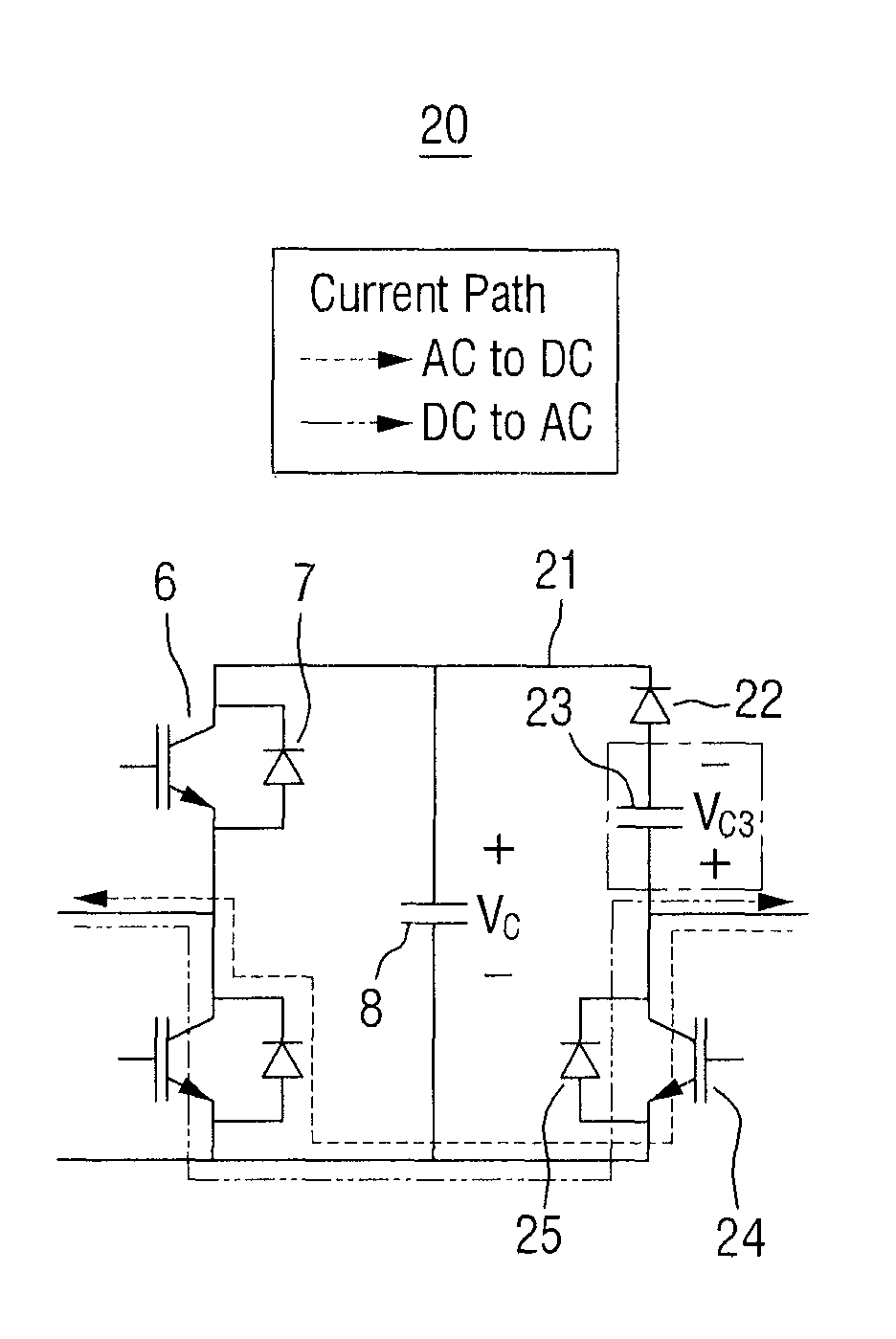
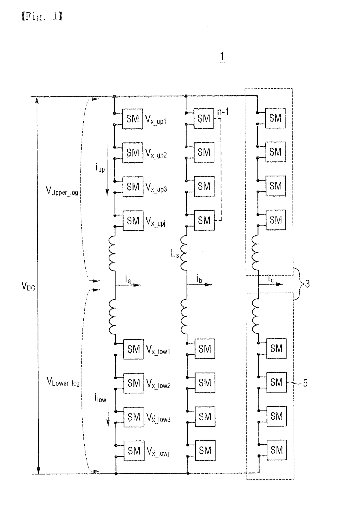
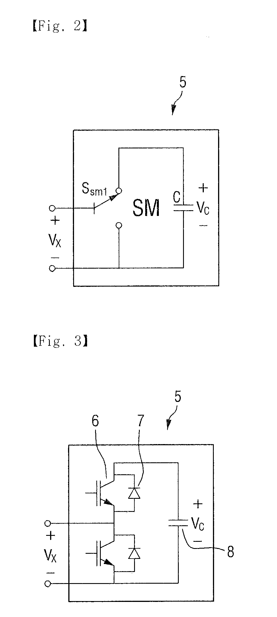
Provided are a multi-level converter having more than one converter arm in which a plurality of sub-modules are connected in series, multi-level converter comprising, a first bypass circuit connected in parallel to at least one sub-module included in more than one converter arm on a first side and including a first switching device, a second bypass circuit connected in parallel to more than one converter arm on a second side and including a diode, a second switching device included in more than one converter arm and having a first end connected in series to at least one sub-module and a second end connected to a first end of first bypass circuit at a single node and a third switching device included in more than one converter arm and having a first end connected in series to at least one sub-module and a second end connected to a first end of second bypass circuit at a single node.

Description

[0001]This application claims priority to Korean Patent Application No. 10-2014-0086812 filed on Jul. 10, 2014, No. 10-2014-0086813 filed on Jul. 10, 2014, No. 10-2014-0150335 filed on Oct. 31, 2014 in the Korean Intellectual Property Office, the disclosure of which is incorporated herein by reference in its entirety.BACKGROUND1. Field of the Invention[0002]The invention relates to a fault current reduction structure of a multi-level converter and an apparatus using the fault current reduction structure, and more particularly, to a fault current reduction structure of a multi-level converter, which is capable of reducing a fault current in the multi-level converter by blocking and bypassing the fault current generated in response to the occurrence of a direct current (DC) fault, and an apparatus using the fault current reduction structure.2. Description of the Related Art[0003]Conventional voltage-type converters generally have a considerable number of switching operations and requi...

Claims


Application Information

Patent Timeline
Patent Type & Authority Patents(United States)
IPC IPC(8): H02M1/32H02H7/122H02M7/483
CPCH02M1/32H02M7/483H02M2007/4835H02M7/4835
Inventor HUR, KYEONKIM, HEE JINKIM, SANG MIN
Owner UNIV IND FOUND UIF
Why Eureka
Eureka Blog
Learn More