Woven fiber optics dental post

a fiber optics and dental post technology, applied in the field of dental posts, can solve the problems of root canal fracture, all-ceramic crown looking gray, tooth structure fragility, etc., and achieve the effects of shortening treatment time, reducing the risk of fracture, and increasing the polymerization of photocurable adhesives

Active Publication Date: 2018-01-23
ILUMI SCI INC +1
View PDF6 Cites 0 Cited by
  • Summary
  • Abstract
  • Description
  • Claims
  • Application Information

AI Technical Summary

Benefits of technology

[0017]By means of the woven fiber component that is formed by intertwining a plurality of fiber optics member, the woven fiber optics dental post of the present invention has higher structure strength. Furthermore, since the light receiving end portion and the light emitting end portion are respectively composed of a plurality of light receiving ends and light emitting ends of the fiber optics members, the intensity and the uniformity of the light emitted from the woven fiber optics dental post increases, and thus the polymerization of the photocurable adhesive can be more complete so as to shorten the treatment time and to achieve better adhesion efficacy.

Problems solved by technology

After tooth root canal treatment, the tooth is structurally fragile due to tooth canal hole or empty space.
Metal post is criticized since it may cause the all-ceramic crown looking gray.
In addition, since the metal post is too hard, it may also cause root canal fracture because it indirectly applies force on the root canal when occluding teeth.
However, if the polymerization of the photocurable adhesive is incomplete, its physical properties may become worse and thus the problem of bad adhesion efficacy, bad attrition resistance, and the bio-incompatibility due to microleakage, which result in clinical treatment failure, may be occur.
However, it is need to improve the weak light intensity due to bad light-guiding efficacy of the conventionally posts, which causes incomplete polymerization of the photocurable adhesive.

Method used


Image

  • Woven fiber optics dental post
  • Woven fiber optics dental post
  • Woven fiber optics dental post

Examples


Embodiment Construction

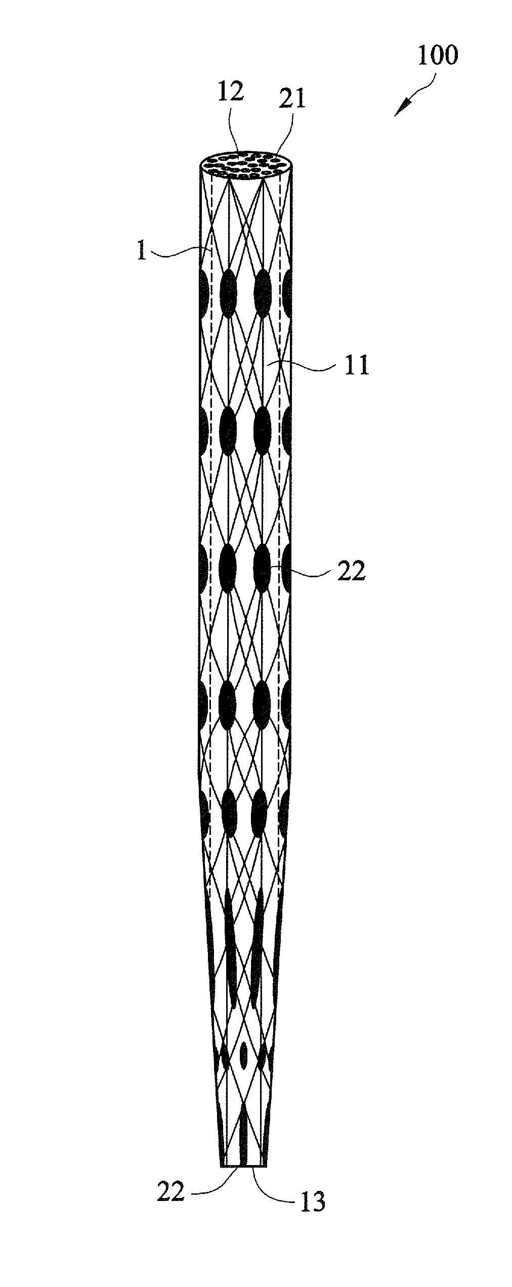
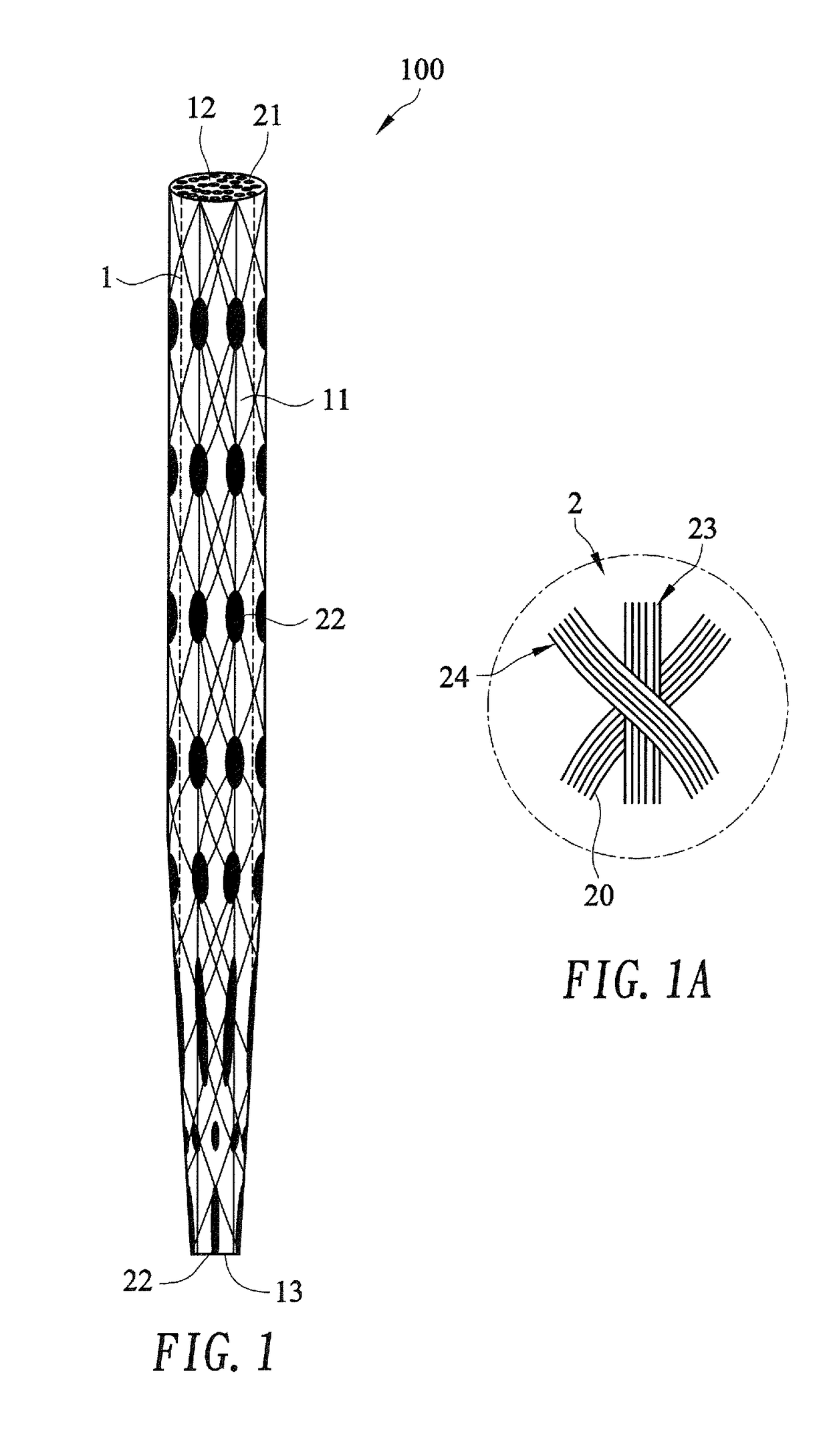
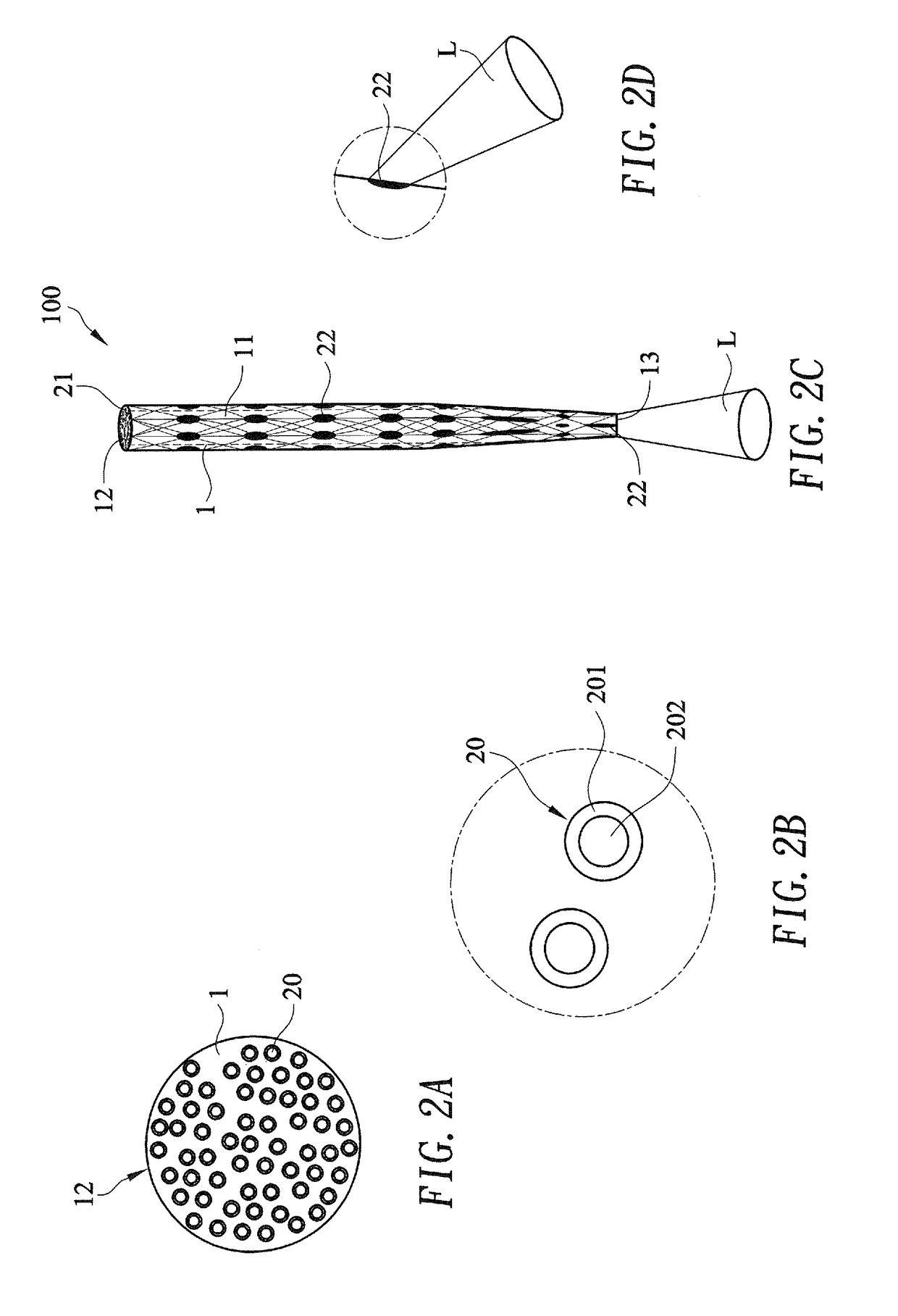
[0036]Refer to FIGS. 1 and 1A and FIGS. 2A to 2D. A woven fiber optics dental post 100 according an embodiment of the present invention includes a post body 1 and a woven fiber component 2.

[0037]The post body 1 is made of resin material. The post body 1 includes a post face 1, an irradiation receiving portion 12, and a bottom 13.

[0038]The woven fiber component 2 is provided within the post body 1. The woven fiber component 2 is formed by intertwining a plurality of fiber optics members 20 and thereby is strong so that the woven fiber optics dental post 100 has higher structure strength. Each fiber optics member 20 has a light receiving end and a light emitting end. A light receiving end portion 21 of the woven fiber component 2 is composed of the light receiving ends of a plurality of the fiber optics members 20. A light emitting end portion 22 of the woven fiber component 2 is composed of the light emitting ends of a plurality of the fiber optics members 20. In this embodiment, the...


PUM


Abstract

A woven fiber optics dental post includes a post body and a woven fiber component. The post body includes a post face, an irradiation receiving portion, and a bottom. The woven fiber component is provided within the post body. The woven fiber component is formed by intertwining a plurality of fiber optics members. A light receiving end portion and a light emitting end portion are respectively composed of a plurality of light receiving ends and light emitting ends of the fiber optics members. The light receiving end portion is appeared on the irradiation receiving portion of the post body for having the woven fiber component receiving a light irradiated at the irradiation receiving portion, and the light emitting end portion is appeared on the post face and / or the bottom of the post body for having the light received by the woven fiber component transmitting to the light emitting end portion to be emitted out of the post face and / or the bottom. Thereby the structure strength and the intensity and the uniformity of the light emitted from the woven fiber optics dental post can be enhanced.

Description

BACKGROUND OF THE INVENTION[0001](a) Technical Field of the Invention[0002]The present invention relates to a dental post, and more particularly to a woven fiber optics dental post.[0003](b) Description of the Prior Art[0004]After tooth root canal treatment, the tooth is structurally fragile due to tooth canal hole or empty space. In order to improve the strength of the tooth, dental post is used to be implanted into the root canal to support and build up the core for the dental prosthesis, such as artificial tooth and dental mouthpiece. Dental posts are generally divided into metal post and fiber post. Metal post is criticized since it may cause the all-ceramic crown looking gray. In addition, since the metal post is too hard, it may also cause root canal fracture because it indirectly applies force on the root canal when occluding teeth. For the reason mentioned above, the demand for fiber post continuously increases in the recent years. The fiber post is made of fiber reinforced ...

Claims


Application Information

Patent Timeline
Patent Type & Authority Patents(United States)
IPC IPC(8): A61C13/15A61C13/30
CPCA61C19/003A61C13/30
Inventor LU, LUKELU, KUAN-YUTOKIZAWA, TOSHIHIROLU, I-CHING
Owner ILUMI SCI INC
Why Eureka
Try Eureka