Air chamber hull
a technology of air chamber and hull, which is applied in the direction of hull parts, vessel construction, marine propulsion, etc., can solve the problems of large cargo ships traveling in the open ocean with large waves, uncomfortable and unsafe riding conditions, and not meeting the criteria of cost and power us
- Summary
- Abstract
- Description
- Claims
- Application Information
AI Technical Summary
Benefits of technology
Problems solved by technology
Method used
Image
Examples
example 1
Air Cushion Hull with a HAR Air Chamber, Stable Walls, Keel Fins, Wave-Piercing Bow
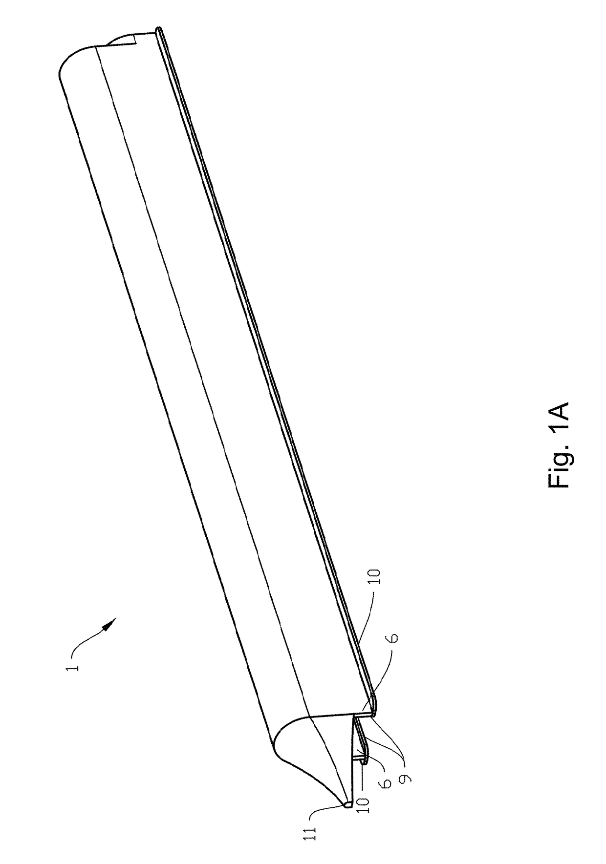
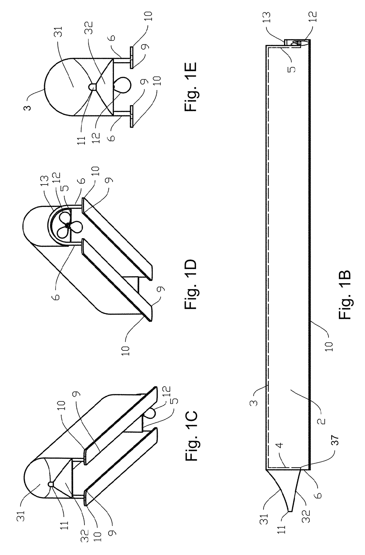
[0206]FIG. 1A-FIG. 1D depict a hull of the invention. The hull comprises an air chamber 2 defined by a fore wall 4, an aft wall 5, an upper wall 3, and opposing sidewalls 6. The foe wall 4 and aft wall 5 are both stable, non-retractable wall. Air injector ports (not shown) are configured to deliver pressurized air to the air chamber to impart an air cushion.
[0207]The sidewalls 6 extend lower than the fore wall 4 and the aft wall 5. The hull comprises fins at the base of each side wall 6 (‘keel fins’). The keel fins are elongated fins that span a greater longitudinal distance (e.g. the entire length of the side wall) than a lateral distance. Specifically, an inner keel fin 9 extends laterally inward from the base of each side wall 6 and an outer keel fin 10 extends laterally outward from the base of each sidewall. The keel fins 9,10 run longitudinally along the entire length of each sidewall 6.
[0208]Th...
example 2
Hull with Recirculating Air Flow
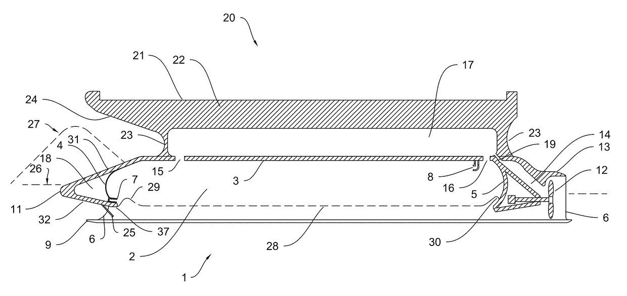
[0211]FIG. 2A-D depict water vessel comprising a deck 20 having top 21, and further comprising a hull 1 of the invention, e.g. as detailed in Example 1, configured with an air chamber 2 having recirculating air flow. The hull comprises an air injector 7 positioned about the base of fore wall 4 aimed astern. The fore wall 4 and the aft wall 5 are both curved and / or provided with a ramped section at the base and upper edges. Such a configuration imparts air flow 33 which travels astern just above the water surface 28 in the air chamber 2 until it reaches the base of the curved aft wall 5, where it ramps up the curve and is redirected forward along the upper wall 3 before reaching the curved fore wall 4, which redirects the air flow 33 back into the path of the air injector 7. Optionally, the hull comprise a second air injector 8 positioned about the upper wall 3 and aimed forward to enhance the recirculating motion of the air 33.
[0212]This configuration...
example 3
Hull with Vented Air Chamber
[0216]In one embodiment, a hull of the invention (e.g. as detailed in Example 1 or Example 2) comprises a vented air chamber. The vented air chamber can be formed by providing one or more valves that allow escape of air from the air chamber 2. The one or more valves can be controlled, e.g. to reduce the air pressure in the air chamber 2 and thereby reduce buoyancy of the hull. Such control of buoyance can be used to dampen the effect of an incoming wave on the hull (e.g. heave or pitch).
[0217]As depicted in FIG. 2C, the hull optionally comprises a plurality of valves that allow escape of air from different location of the air chamber 2, such as a first valve 15 provided at a first location near the bow or other forward location and a second valve 16 provided at a second location near the stern or other location astern of the first location. In such an embodiment, the valves 15,16 can be differentially controlled to provide an instantaneous reduction air c...
PUM
 Abstract
Description
Claims
Application Information
 - R&D
- Intellectual Property
- Life Sciences
- Materials
- Tech Scout
- Unparalleled Data Quality
- Higher Quality Content
- 60% Fewer Hallucinations
Browse by: Latest US Patents, China's latest patents, Technical Efficacy Thesaurus, Application Domain, Technology Topic, Popular Technical Reports.
© 2025 PatSnap. All rights reserved.Legal|Privacy policy|Modern Slavery Act Transparency Statement|Sitemap|About US| Contact US: help@patsnap.com


