
System and method for robot supervisory control with an augmented reality user interface

a robot and user interface technology, applied in the field of robot supervisory control, can solve the problems of not taking into account the necessary adjustments, unable to align the robot posture with visual input, and unable to achieve the necessary adjustments

Active Publication Date: 2018-01-30
HRL LAB
View PDF4 Cites 18 Cited by
  • Summary
  • Abstract
  • Description
  • Claims
  • Application Information

AI Technical Summary

Benefits of technology

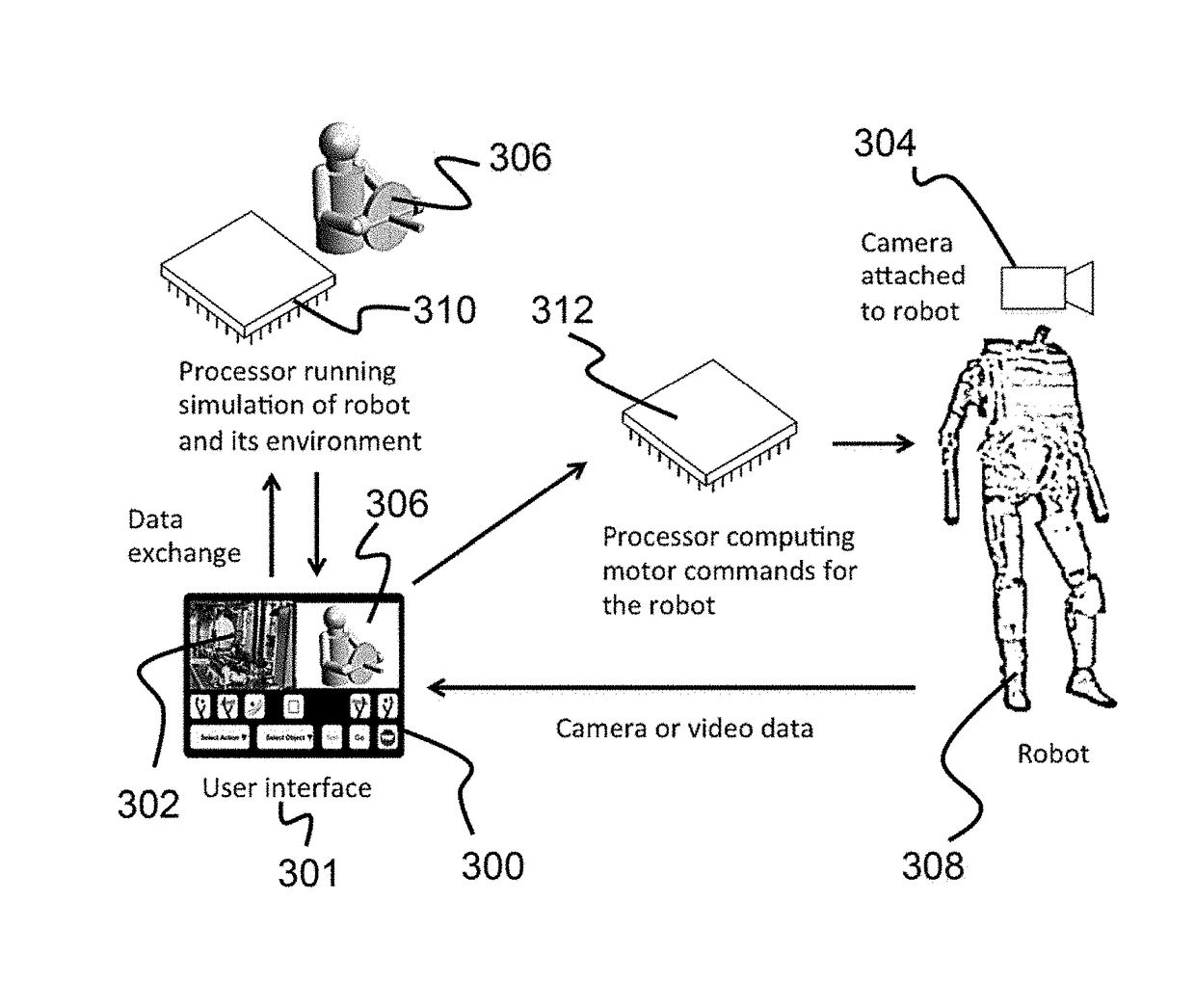
The patent describes a system for controlling a robot using an operator device. The operator device has a processor and memory, and can receive camera imagery and 3D data from a robot-mounted camera and sensor. The system can display a user interface with a 2D view of the scene and 3D data. The user interface can also allow users to add or modify object markers in the scene, and to choose commands to control the robot. The system can also show a simulation of the robot performing the chosen command, and can provide an overlay display of the dynamic scene. The technical effects of the patent include improved visualization of the robot's surroundings, improved control and manipulation of objects in the scene, and better representation of the robot's actions.

Problems solved by technology

Autonomous robots typically suffer from limited situational awareness.
However, the limitation of this approach is that aligning a robot posture with visual input is very tedious.
Moreover, rigid postures do not account for necessary adjustments to cope with uncertain contact surfaces and dynamic obstacles (such as moving objects).
While generally operable, many issues remain such as, inadequate resolution, lag in the video image, and lag in the mechanical and movement responses of the robot.

Method used


Image

  • System and method for robot supervisory control with an augmented reality user interface
  • System and method for robot supervisory control with an augmented reality user interface
  • System and method for robot supervisory control with an augmented reality user interface

Examples


Embodiment Construction

[0025]The present invention relates to a system for robot supervisory control and, more particularly, to a system for robot supervisory control through the use of perception-based markers and augmented reality. The following description is presented to enable one of ordinary skill in the art to make and use the invention and to incorporate it in the context of particular applications. Various modifications, as well as a variety of uses in different applications will be readily apparent to those skilled in the art, and the general principles defined herein may be applied to a wide range of aspects. Thus, the present invention is not intended to be limited to the aspects presented, but is to be accorded the widest scope consistent with the principles and novel features disclosed herein.

[0026]In the following detailed description, numerous specific details are set forth in order to provide a more thorough understanding of the present invention. However, it will be apparent to one skill...


PUM


Abstract

Described is a system for robot supervisory control. The system includes an operator device that receives camera imagery from a camera mounted on a robot and three-dimensional (3D) data from a 3D sensor mounted on the robot. The user interface displays a two-dimensional (2D) view of the scene from the camera and 3D sensor data. One or more object markers of objects in the scene are overlaid on the 2D view or 3D sensor data. Viewing the scene, the user can choose a robotic action from a library of actions, which generates a simulation of the robot performing the selected action. The simulation is then rendered and overlaid on top of the 3D sensor data. Moreover, the simulation shows the expected variability of the robot's action. Based on the simulation's outcome, the user can approve and trigger the execution of the action in the real robot.

Description

CROSS-REFERENCE TO RELATED APPLICATIONS[0001]This is a non-provisional application of U.S. Ser. No. 62 / 153,931, filed on Apr. 28, 2015, the entirety of which is incorporated by reference as though fully set forth herein.BACKGROUND OF INVENTION[0002](1) Field of Invention[0003]The present invention relates to a system for robot supervisory control and, more particularly, to a system for robot supervisory control through the use of perception-based markers and augmented reality.[0004](2) Description of Related Art[0005]Autonomous robots typically suffer from limited situational awareness. To provide autonomous control, the prior art generally relies upon the use of programming robots by defining waypoints. For example, interactive interfaces allow the specification of multiple robot arm poses. However, the limitation of this approach is that aligning a robot posture with visual input is very tedious. Moreover, rigid postures do not account for necessary adjustments to cope with uncert...

Claims


Application Information

Patent Timeline
IPC IPC(8): G05D1/00H04N5/225G06T11/60G06F3/0484B25J9/16G05D1/02B25J19/02
CPCG05D1/0038B25J9/1689B25J19/023G05D1/0016G05D1/0251H04N13/0203H04N5/2253G06T11/60G06F3/04845G06F3/04842Y10S901/01G05D2201/0217H04N13/204G05B2219/40B25J9/1697B25J9/1671G05B2219/39H04N23/54
Inventor HOFFMANN, HEIKODAILY, MICHAEL J.
Owner HRL LAB
Learn More