
LED display apparatus and LED pixel error detection method thereof

a technology of led display and error detection method, which is applied in the direction of lighting apparatus, instruments, light sources, etc., can solve the problems of inconvenient operation, inability to determine the necessity of a/s, and unknowable, and achieve the effect of efficient error detection method

Active Publication Date: 2018-01-30
SAMSUNG ELECTRONICS CO LTD
View PDF7 Cites 2 Cited by
  • Summary
  • Abstract
  • Description
  • Claims
  • Application Information

AI Technical Summary

Benefits of technology

[0010]An aspect of one or more exemplary embodiments relates to an LED display apparatus which accurately detects a position of an LED element where an error occurs by determining position information of the LED element and determining whether after service (A / S) is required, and an error detection method thereof. In addition, by adjusting a brightness of LED elements around the LED element in which the error occurs, there is provided a method for maintaining average brightness in an even manner.
[0036]As described above, according to various exemplary embodiments, an efficient error detection method for an LED element can be provided by detecting an LED element where an error occurs, detecting accurate position information of the element, and transmitting notification information for a specific case based on the position information. In addition, by adjusting the brightness of LED elements around the LED element where an error occurs, an average brightness may be maintained, and, therefore, a user's error recognition when viewing the LED from a distance can be minimized and a problem of uniformity of brightness can be solved.

Problems solved by technology

In the related art, A / S is provided only when a user detects a problem, and therefore, there is a drawback that the necessity of A / S cannot be determined until an operator observes or determines a current state.
However, in the related art, when an LED element error occurs, it is determined that A / S needs to be provided regardless of visibility problems, and, thus, unnecessary A / S is provided.
In addition, in the related art, even when an LED element error is detected, information on an accurate position of an LED element where the error occurs is not known, and efficient A / S is not provided.

Method used


Image

  • LED display apparatus and LED pixel error detection method thereof
  • LED display apparatus and LED pixel error detection method thereof
  • LED display apparatus and LED pixel error detection method thereof

Examples


Embodiment Construction

[0049]Certain exemplary embodiments will now be described in greater detail with reference to the accompanying drawings.

[0050]In the following description, the same drawing reference numerals are used for the same elements even in different drawings. The matters defined in the description, such as detailed construction and elements, are provided to assist in a comprehensive understanding of one or more exemplary embodiments. Thus, it is apparent that one or more exemplary embodiments can be carried out without those specifically defined matters. Also, well-known functions or constructions are not described in detail since they would obscure the disclosure with unnecessary detail.

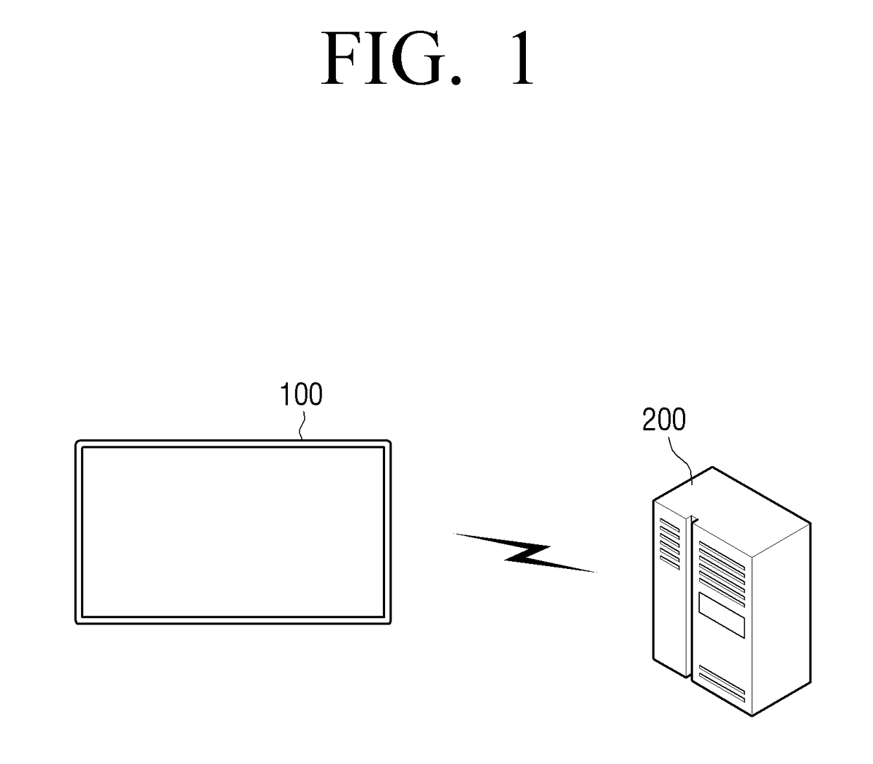
[0051]FIG. 1 is a view illustrating a remote LED detection system according to an exemplary embodiment. Referring to FIG. 1, the LED remote detection system includes an LED display apparatus 100 and an operating terminal 200.

[0052]The LED display apparatus 100 may be embodied as various display apparatuses s...


PUM


Abstract

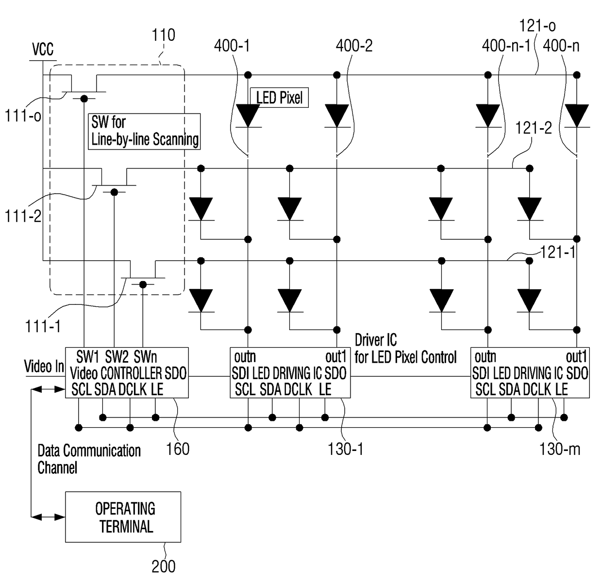
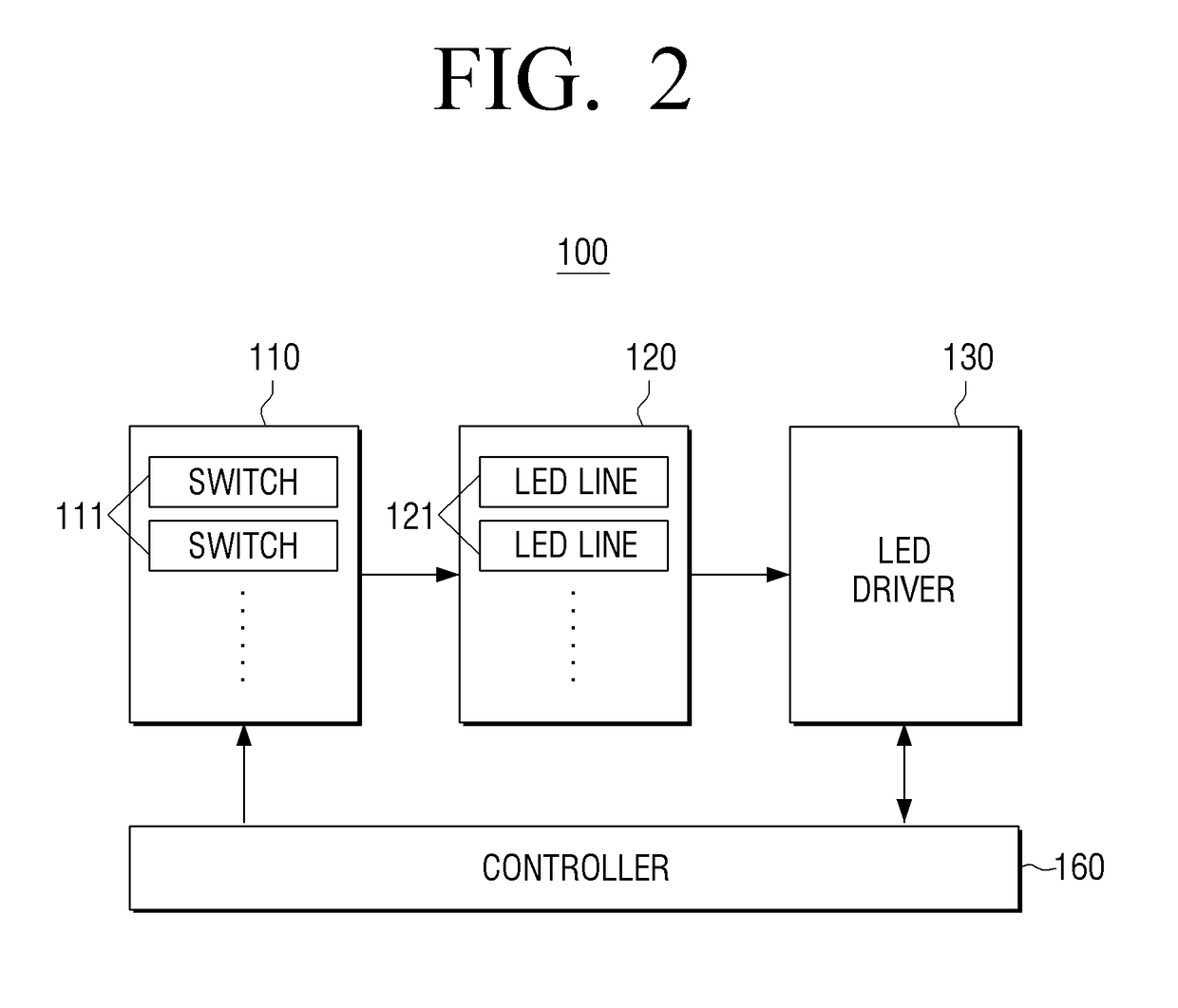
A light emitting diode (LED) display apparatus, including: a plurality of LED lines including a plurality of LEDs; a plurality of switches connected to respective LED lines among the plurality of LED lines; a controller configured to sequentially supply power to the plurality of LED lines by sequentially turning on and off the plurality of switches; and an LED driver configured to detect an error state of an LED from the plurality of LEDs by estimating current flowing through the plurality of LED lines, and to provide the controller with a result of the detection.

Description

CROSS-REFERENCE TO RELATED APPLICATIONS[0001]This application claims priority from Korean Patent Application No. 10-2014-0123752, filed in the Korean Intellectual Property Office on Sep. 17, 2014, the disclosure of which is incorporated herein by reference in its entirety.BACKGROUND[0002]1. Field[0003]Aspects of one or more exemplary embodiments relate to an LED display apparatus and an error detection method thereof, and more particularly, to an LED display apparatus which may accurately detect a location of an LED element where an error occurs, and remotely determine whether or not after service (A / S) is required, and an error detection method thereof.[0004]2. Description of the Related Art[0005]Display apparatuses using light emitting diodes (LEDs) are known. Compared to some other display elements, LED elements have some technical advantages, such as excellent brightness, outdoor visibility, and easy scaleup.[0006]Recently, large LED display apparatuses have been available at a ...

Claims


Application Information

Patent Timeline
Patent Type & Authority Patents(United States)
IPC IPC(8): H05B37/02H05B37/03G09G3/32
CPCG09G3/32G09G2330/12G09G2320/0295
Inventor HA, TAE-HYEUNHYEON, BYEONG-CHEOL
Owner SAMSUNG ELECTRONICS CO LTD
Learn More