Method for ascertaining a position of a rotor of an electrical machine

a technology of electrical machines and rotors, which is applied in the direction of electronic commutation motor control, electric generator control, instruments, etc., can solve the problems of rotor rotation misfiring of internal combustion engines, and fuel being initially delivered in the wrong direction, so as to prevent the rotor

Inactive Publication Date: 2018-02-06
ROBERT BOSCH GMBH
View PDF29 Cites 0 Cited by
  • Summary
  • Abstract
  • Description
  • Claims
  • Application Information

AI Technical Summary

Benefits of technology

[0014]When the position of the rotor is determined relative to the stator, it is advantageous to allow for a magnetic field strength generated by one or a plurality of permanent magnet(s) of the rotor or of the stator in the area of the at least one winding. The magnetic field strength of the permanent magnets in the area of the winding is a function of the distance of the permanent magnets among themselves and to the winding. For an electrical machine, however, the exact configuration is known that may be used to calculate the magnetic field strength in the area of the winding, for example. However, it is also possible to use test measurements, for example, to ascertain the magnetic field strength in the area of the winding. Thus, the position of a rotor may be thereby inferred very accurately as a function of the change in the inductance.
[0015]The ascertained position of a rotor relative to the stator is preferably used for an initial commutation process during an operation of the electrical machine. It is thereby possible to prevent the rotor from potentially rotating briefly in the wrong direction when the electrical machine is switched on.
[0018]The method is advantageously implemented as a computer program, since this entails especially low costs, particularly when an executing control unit is also used for other tasks and is, therefore, present anyway. Suitable storage media for providing the computer program include, in particular, magnetic, optical and electrical memories, for example, such as hard disks, flash memories, EEPROMs, DVDs, inter alia. A program may also be downloaded over computer networks (Internet, intranet, etc.).

Problems solved by technology

As a result, fuel can initially be delivered in the wrong direction, particularly when such an electrical machine is used in fuel-delivery systems, such as in a motor vehicle.
The magnetic field strength induced by this current suffices for ascertaining the change in the inductance, however, not for moving the rotor against the frictional force.
A rotor rotation in the wrong direction is disadvantageous, especially in the case of fuel pumps in motor vehicles, since fuel is thereby delivered in the wrong direction, i.e., away from an internal combustion engine, instead of toward an internal combustion engine.
This could result in misfirings during operation of the internal combustion engine.

Method used


Image

  • Method for ascertaining a position of a rotor of an electrical machine
  • Method for ascertaining a position of a rotor of an electrical machine
  • Method for ascertaining a position of a rotor of an electrical machine

Examples


Embodiment Construction

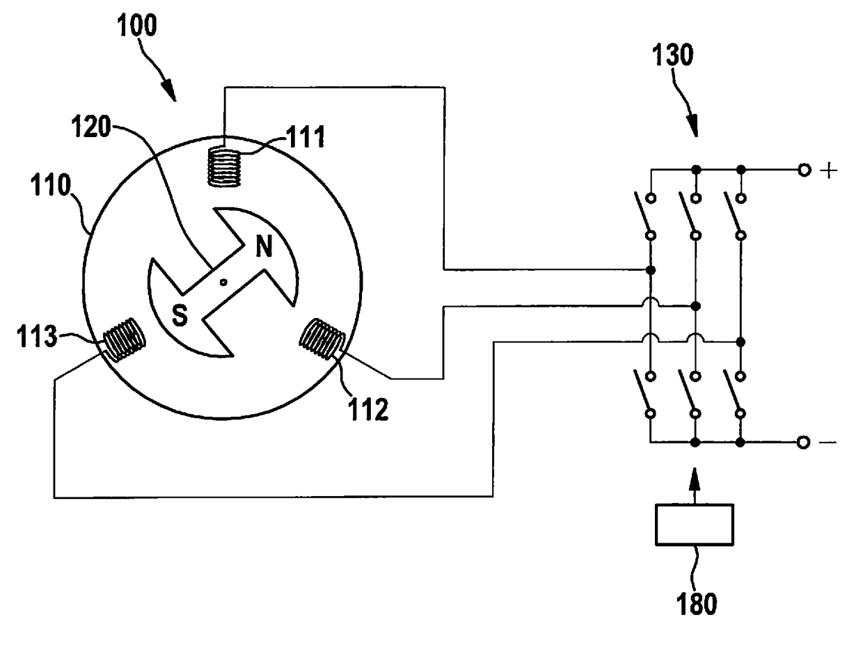
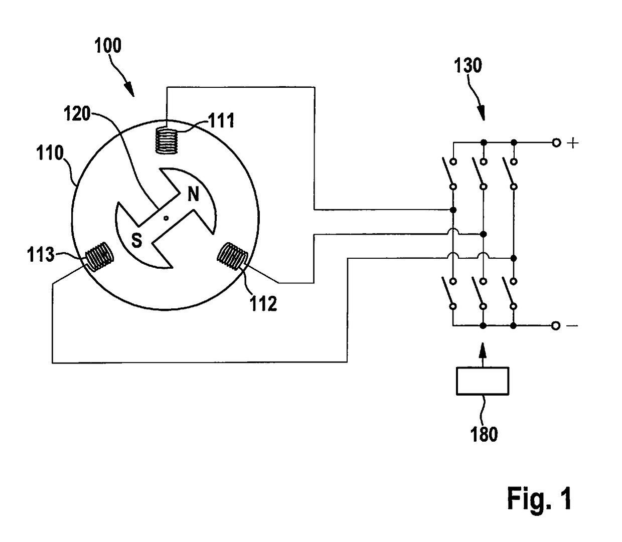
[0024]Schematically and in simplified form, FIG. 1 shows an electrical machine 100 that is suited for implementing a method according to the present invention. Here, electrical machine 100 is a brushless direct-current motor.

[0025]Electrical machine 100 has a stator 110, which, in turn, exemplarily includes three windings 111, 112, 113. Electrical machine 100 also has a rotor 120, which includes a permanent magnet that is apparent by the designations N and S for north pole and south pole.

[0026]Also shown is a circuit configuration 130 having three windings 111, 112, 113 connected thereto. The circuit configuration has six switches for connecting the three windings alternatingly to positive and negative voltage, for example. For this purpose, processing unit 180 may drive circuit configuration 130 and, in particular, the switches. In other respects, the operating principle of such an electrical machine is known per se and will, therefore, not be described in greater detail here.

[0027...


PUM


Abstract

A method for ascertaining a position of a rotor relative to a stator of an electrical machine having a permanently excited rotor and a plurality of windings for the stator or vice versa; in response to an energization of at least one of the windings, a change in an inductance of the winding being ascertained; and, on the basis of the change in the inductance of the winding, the position of the rotor being ascertained relative to the stator.

Description

CROSS REFERENCE[0001]The present application claims the benefit under 35 U.S.C. § 119 of German Patent Application No. DE 102015214596.4 filed on Jul. 31, 2015, which is expressly incorporated herein by reference in its entirety.FIELD[0002]The present invention relates to a method for ascertaining a position of a rotor of an electrical machine, as well as to a processing unit and a computer program for the implementation thereof.BACKGROUND INFORMATION[0003]Electrical machines having a permanently excited rotor and a winding for the stator, in particular what are generally known as brushless direct-current motors, can be controlled by a microcontroller, for example. In response to switching off of the electrical machine, the rotor thereof can reach any position at all. Even here, there is generally no preferential position.[0004]Since an initial commutation must always be performed when the electrical machine is switched on, the situation can, therefore, arise whereby the rotor at fi...

Claims


Application Information

Patent Timeline
Patent Type & Authority Patents(United States)
IPC IPC(8): G01D5/20H02P9/00
CPCG01D5/20H02P9/009G01D5/2006H02P6/186
Inventor HERMES, HENNINGSCHMITT, FLORIANFOERCH, ULRICHSCHULZ, UDOFRIEDL, TOBIASMUELLER, ULFJENNE, ACHIM
Owner ROBERT BOSCH GMBH
Why Eureka
Try Eureka