Combined crystal retainer and contact system for deposition monitor sensors

a monitor and crystal retainer technology, applied in resistance/reactance/impedence, instruments, material analysis, etc., can solve the problems of loss of q, affecting the measurement effect, and the measurement circuit is substantially less able to make a consistent frequency measurement, etc., to increase the optical communication channel or spectral based chemical analysis, improve the wear resistance of the machine component, and improve the effect of production

Active Publication Date: 2016-11-29
INFICON INC
View PDF4 Cites 0 Cited by
  • Summary
  • Abstract
  • Description
  • Claims
  • Application Information

AI Technical Summary

Benefits of technology

[0002]A quartz crystal microbalance is often used as part of a control system in order to optimize the production of specialty thin film coatings that may be used for a wide variety of functional and decorative uses. Exemplary uses of these film coatings cover a fairly wide spectrum that may include those aimed at increasing a machine component's wear resistance, narrow band optical filtering for increasing optical communication channels or spectral based chemical analysis, enhancement of light transmission through lenses and windows, and enhancing the reflection of mirrors and reducing the light reflected from a transparent surface or simply to apply a color; e.g. create a low cost substitute for gold color, among a myriad of other possible uses. The quartz crystal microbalance that is used for optimizing these processes is commonly known as a deposition process controller. A deposition process controller is used for real time sensing of the precise amount of material that is incident onto and subsequently adheres to a face of a resonantly vibrating piezoelectric crystal. The deposition parameters commonly sensed with this technology are the rate of deposition and total thickness. The crystal microbalance's sensor function relates to the frequency reduction of the composite resonator (monitor crystal plus deposited material) caused by the mass added to the vibrating piezoelectric plate that is partially exposed to the deposition. The foregoing application has a generally well-accepted formulation and is clearly described in chapter 2 of “Applications of Piezoelectric Quartz Crystal Microbalances” by Lu and Czanderna (Elsevier, first edition pp. 19-57) the entire contents of which are herein incorporated. In practice, the quartz crystal microbalance is located among or nearby the substrates that are being coated and is used as a surrogate substrate, allowing for precise inference of the amount of material added to the substrates by careful calculation based on the directional distribution of the material leaving a deposition source and use of the geometric relationships between the deposition source, substrates and the monitor crystal.
[0003]The precise and accurate measurement of the monitor crystal's frequency is an essential component of deposition control. The measurement of frequency is commonly accomplished according to two (2) basic techniques or methods. The first technique is referred to as the so called “active” method in which the monitor crystal and its adlayer becomes part of an oscillator circuit and the resulting frequency is measured by one of many possible ways of measuring frequency. One commonly employed method used to measure frequency employs an independent precision reference oscillator of known frequency to establish a precise and repetitive period of time by counting this oscillator's pulses to a predetermined fixed number. This process of repeatedly counting a fixed number of the precision oscillator's pulses establishes an exactly recurring period of time. A second counter is started and stopped by this recurring period that similarly measures the pulses from the resonating monitor crystal. This method of counting the number of measurement crystal pulses over a fixed period of time permits a very accurate measurement of the monitor crystal's frequency and is commonly known as the “period measurement technique”. The change of the monitor crystal's frequency is related to the mass added, so therefore knowing the density of the added material, the thickness may be inferred. Noting the change of thickness between successive recurring measurement periods, the rate of material deposition may then be calculated. This measured deposition rate is often used as the measured variable in a control system that manipulates the power to the deposition source such that the deposition rate can be stabilized or in some cases changed and manipulated in desired and advantageous ways.

Problems solved by technology

When the effective crystal Q deteriorates, the measurement circuits are substantially less able to make a consistent frequency measurement and the control system is compromised by this source of noise.
The adherence and growth of the deposition material on the monitor crystal is, by its nature, a dissipative process due to its lack of piezoelectric contribution, acoustic dissipation due to crystalline defects, and in many cases the introduction of tensile or compressive stresses to the composite resonator.
The sharpness of the monitor crystal's resonance, which is related to the quality factor Q, is known to be reduced as the amount of deposition material is increased on the face of the monitor crystal and this loss of Q is known to increase the perceived noise of the measurement.
Loss of signal strength due to high resistance from loose or corroded connections or a parasitic electrical leak caused by conductive or capacitive leakage through deposited material from the applied radio frequency voltage and the return path allows a portion of the voltage to bypass the monitor crystal and is thereby detrimental to the optimal function of the measurement circuit.
Clearly, a single leaf spring contact system having fewer pieces and contact junctions would be electrically superior, but without a retainer to hold the monitor crystal in proper relationship to its desired position in the crystal holder package all of the aforementioned practical problems associated with monitor crystal replacement are strongly manifested.
When the positioning of the monitor crystal's face with the holder's crystal seat is not automatically aided by the local gravity field and instead the local gravity field tends to tilt or dislodge the monitor crystal, the installation or removal of the holder package becomes extremely difficult.
It is logical to assume that when any process is difficult and unpleasant, it is more likely to be performed improperly than when the process is easy and simple.
While it may be possible to add a retainer component to a design, such as that disclosed by Lu et al., it is found in practice that the spring contact used to make contact with the monitor crystal is susceptible to damage during routine cleaning; for example, a vacuum cleaning nozzle wiping across the sensor's holder cavity and reaching the contact spring causing distortion or breakage.
The replacement of the contact spring requires tools, and or soldering and has to be performed in a position that is often difficult to reach or in an orientation that makes replacement and removal times long and frustrating.
If soldering is required to repair the spring, the associated use of flux is a further complication because the applied flux must be thoroughly and meticulously removed after soldering and before processing can resume in order to avoid flux-caused contamination of the coating process and apparatus.

Method used


Image

  • Combined crystal retainer and contact system for deposition monitor sensors
  • Combined crystal retainer and contact system for deposition monitor sensors
  • Combined crystal retainer and contact system for deposition monitor sensors

Examples


Embodiment Construction

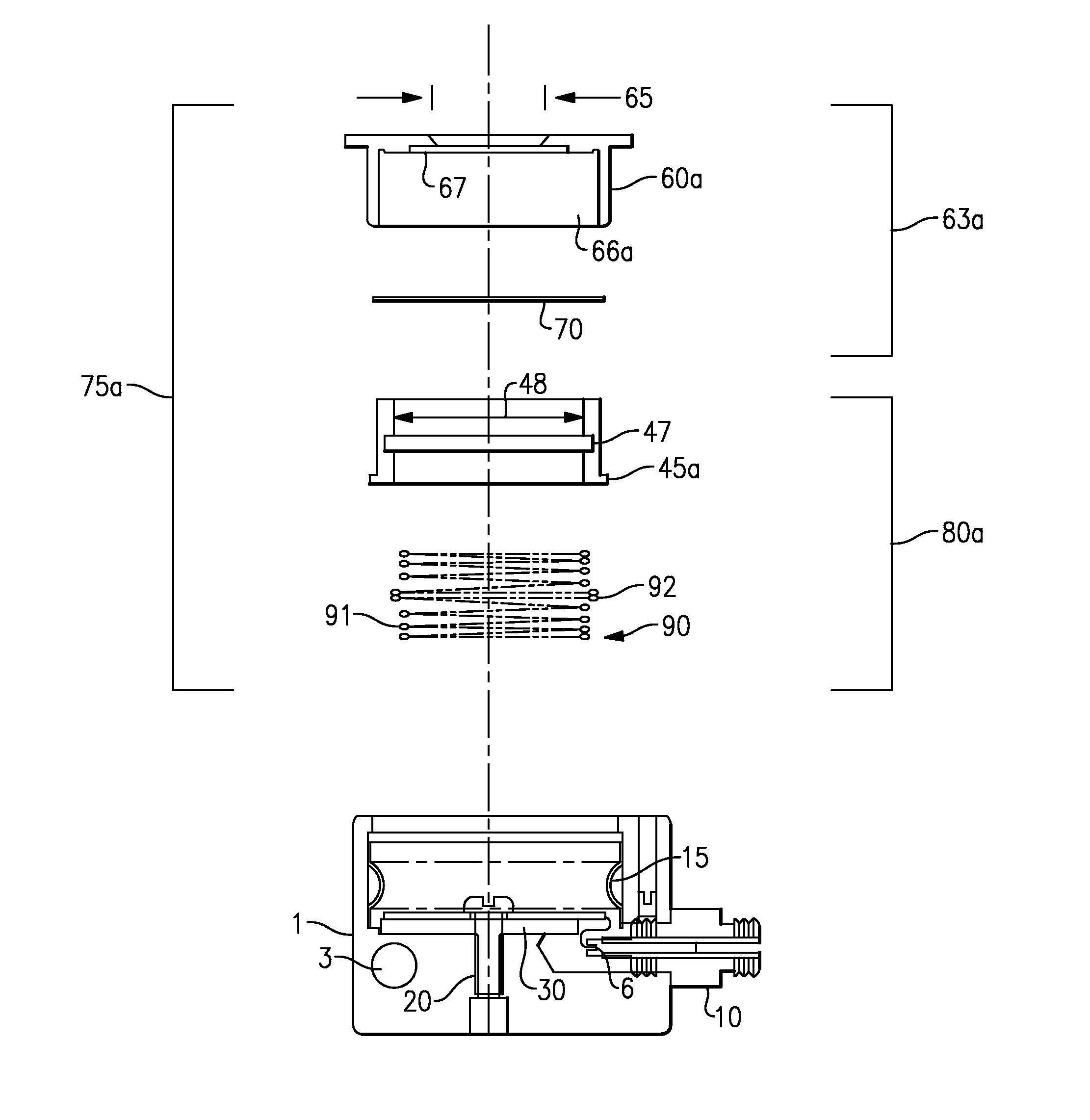
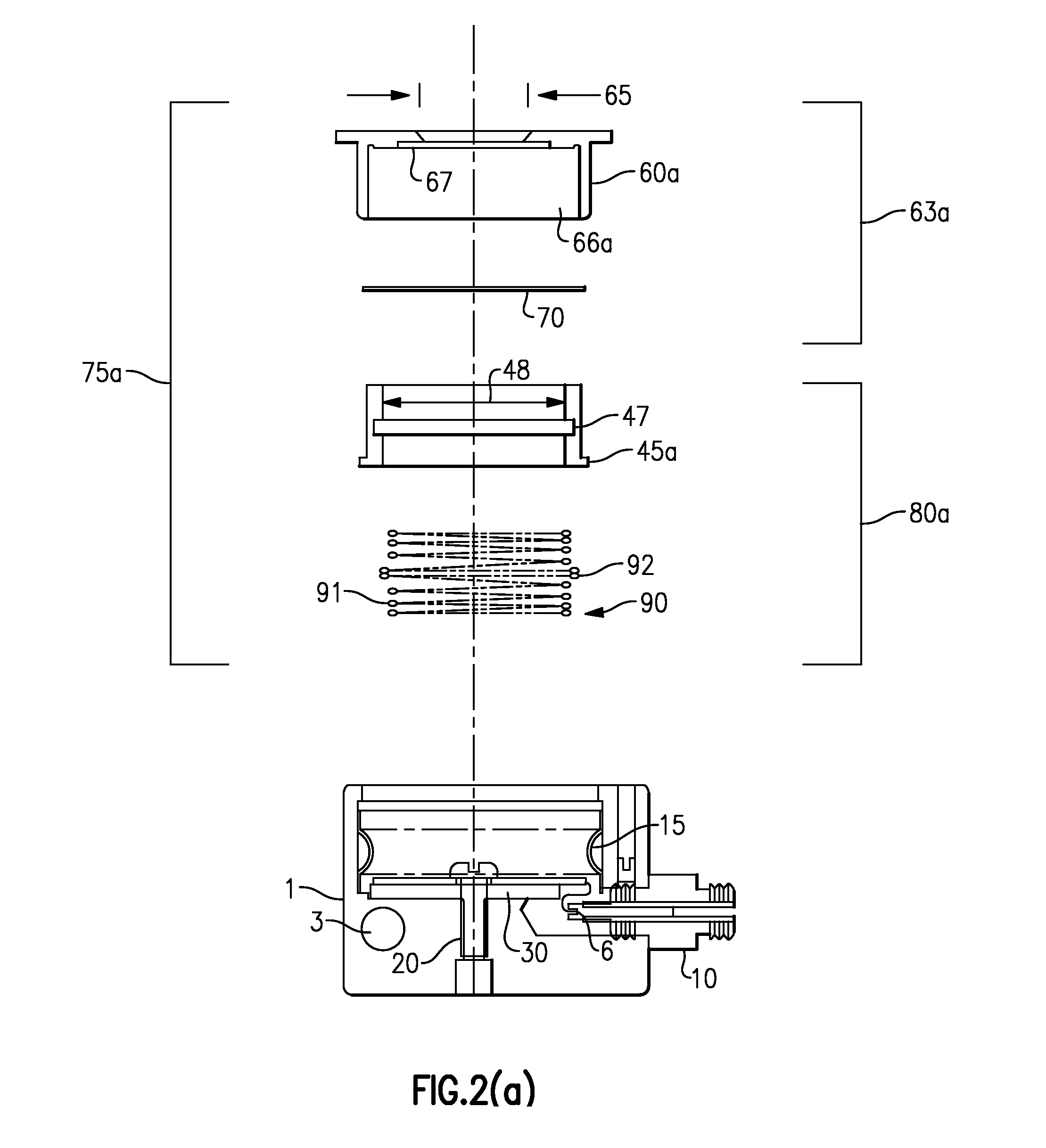
[0042]The following description relates to several embodiments of a system for retaining a monitor crystal that is used in conjunction with a deposition process monitor, the system further insuring electrical contact between an electrical source and a face of a retained monitor crystal, such as a piezoelectric crystal. Throughout the course of discussion, several terms are used in order to describe the invention in accordance with the accompanying drawings. These terms, such as “front”, “rear”, “lateral”, “upper”, “lower”, “proximal”, “distal” and the like are merely intended to provide a suitable frame of reference with regard to the accompanying drawings. These terms are not intended to otherwise inhibit the scope of the present invention, including the claims. In addition, the included drawings are not necessarily to scale and are simply intended to clearly illustrate the salient features of the invention.

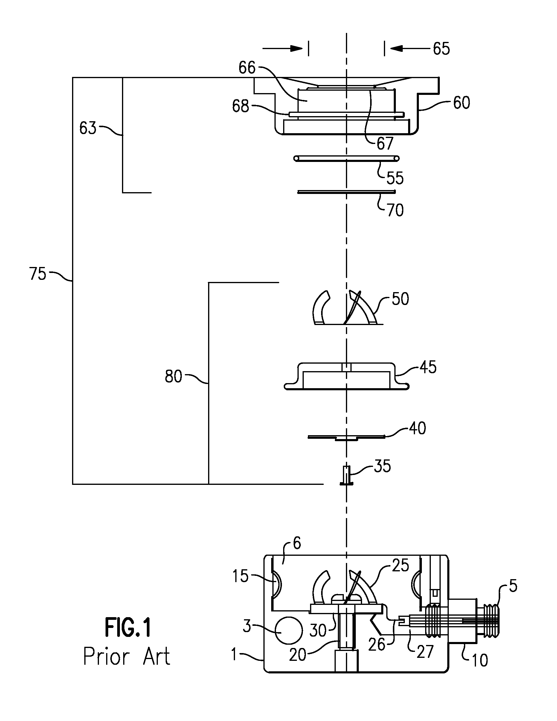
[0043]A typical prior art version of a deposition sensor that incorporates ...


PUM

PropertyMeasurementUnit
diameteraaaaaaaaaa
electricalaaaaaaaaaa
flexibleaaaaaaaaaa

Abstract

A combination retainer and electrical contact mechanism for a deposition monitor sensor includes a sensor body and a removable flexible electrical contact spanning between a fixed electrical (contact) element in the sensor's body and one face of an associated monitor crystal. A retainer insulates or insures electrical isolation of the spanning electrical contact from unwanted contact to electrically grounded components in which at least one of the retainer and crystal holder include features that maintain the electrical contact with the retainer in order to provide a single mechanism.

Description

TECHNICAL FIELD[0001]This application relates generally to the field of material processing and more specifically to a combined monitor crystal retainer and electrical contact system, as well as a related method for retaining a monitor crystal while providing electrical contact therewith for use in deposition monitor sensors.BACKGROUND AND SUMMARY[0002]A quartz crystal microbalance is often used as part of a control system in order to optimize the production of specialty thin film coatings that may be used for a wide variety of functional and decorative uses. Exemplary uses of these film coatings cover a fairly wide spectrum that may include those aimed at increasing a machine component's wear resistance, narrow band optical filtering for increasing optical communication channels or spectral based chemical analysis, enhancement of light transmission through lenses and windows, and enhancing the reflection of mirrors and reducing the light reflected from a transparent surface or simp...

Claims


Application Information

Patent Timeline
Patent Type & Authority Patents(United States)
IPC IPC(8): G01R27/28H01L41/053H01L41/047G01N29/24
CPCG01N29/2443H01L41/0475H01L41/053H10N30/875H10N30/88
Inventor GOGOL, JR., CARL A.
Owner INFICON INC
Why Eureka
Try Eureka