
Electrical box with adjustable sleeve

a technology of electrical boxes and sleeves, applied in the field of electrical boxes, can solve the problems of structural components, undetectable receding or protruding from the substrate of the open face of the electrical box, and the thickness of the wall or ceiling substrate may vary or may be unknown, so as to facilitate the adjustment minimize the complexity of assembly of the electrical box, and maximize the ease of adjusting the electrical box

Active Publication Date: 2018-02-13
ALLIED MOLDED PRODS
View PDF6 Cites 9 Cited by
  • Summary
  • Abstract
  • Description
  • Claims
  • Application Information

AI Technical Summary

Benefits of technology

The adjustable sleeve system simplifies the adjustment process, minimizes assembly complexity, and ensures a consistent vapor seal across varying substrate thicknesses, enhancing energy conservation in building construction by allowing for precise alignment and secure mounting without complete repositioning or retrofitting.

Problems solved by technology

However, sometimes a thickness of the wall or the ceiling substrate may vary or may be unknown when installing the electrical box during construction.
This unknown variable may cause the open face of the electrical box to undesirably recede or protrude from the substrate.
A repositioning of the electrical box may require completely removing the fastening devices from the mounting structures or the structural components which can be inefficient.
However, in order to correct the receding or protruding electrical box, adjustment of the entire electrical box may interfere with proper sealing due to the flange improperly aligning with the substrate.

Method used


Image

  • Electrical box with adjustable sleeve
  • Electrical box with adjustable sleeve
  • Electrical box with adjustable sleeve

Examples


Embodiment Construction

[0019]The following detailed description and appended drawings describe and illustrate various exemplary embodiments of the invention. The description and drawings serve to enable one skilled in the art to make and use the invention, and are not intended to limit the scope of the invention in any manner. In respect of the methods disclosed, the steps presented are exemplary in nature, and thus, the order of the steps is not necessary or critical. For purposes of this disclosure and the claims herein, the terms “right,”“left,”“front,” and “back” (or “forward” and “rearward”) respectively indicate directions which are relative to the arrangement of the electrical box assembly with respect to a building substrate.

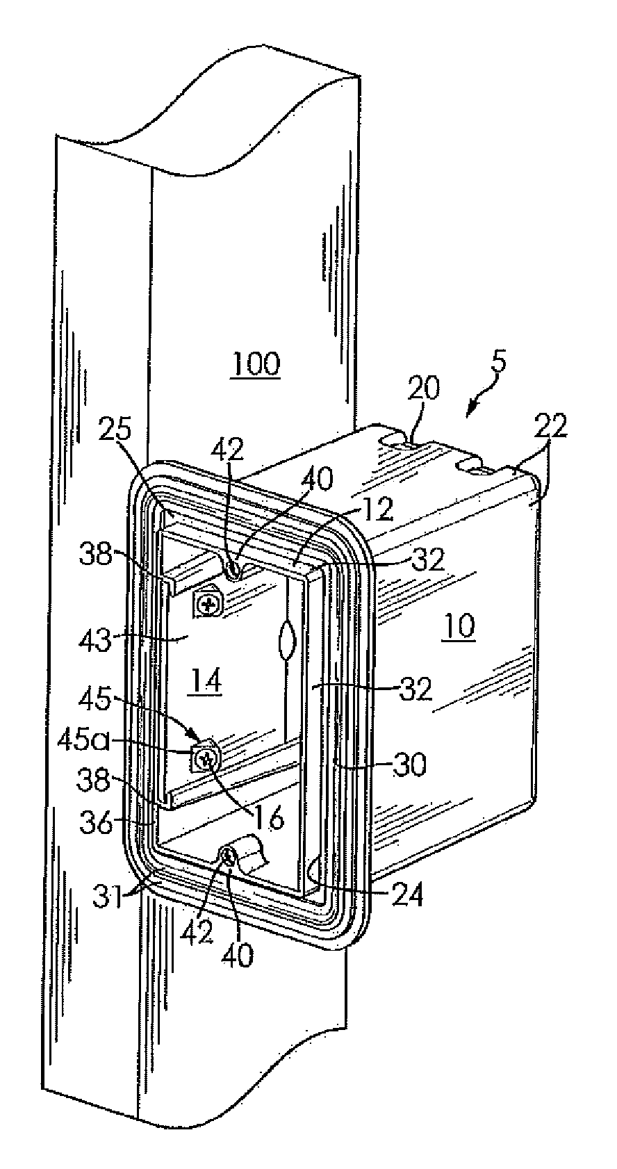
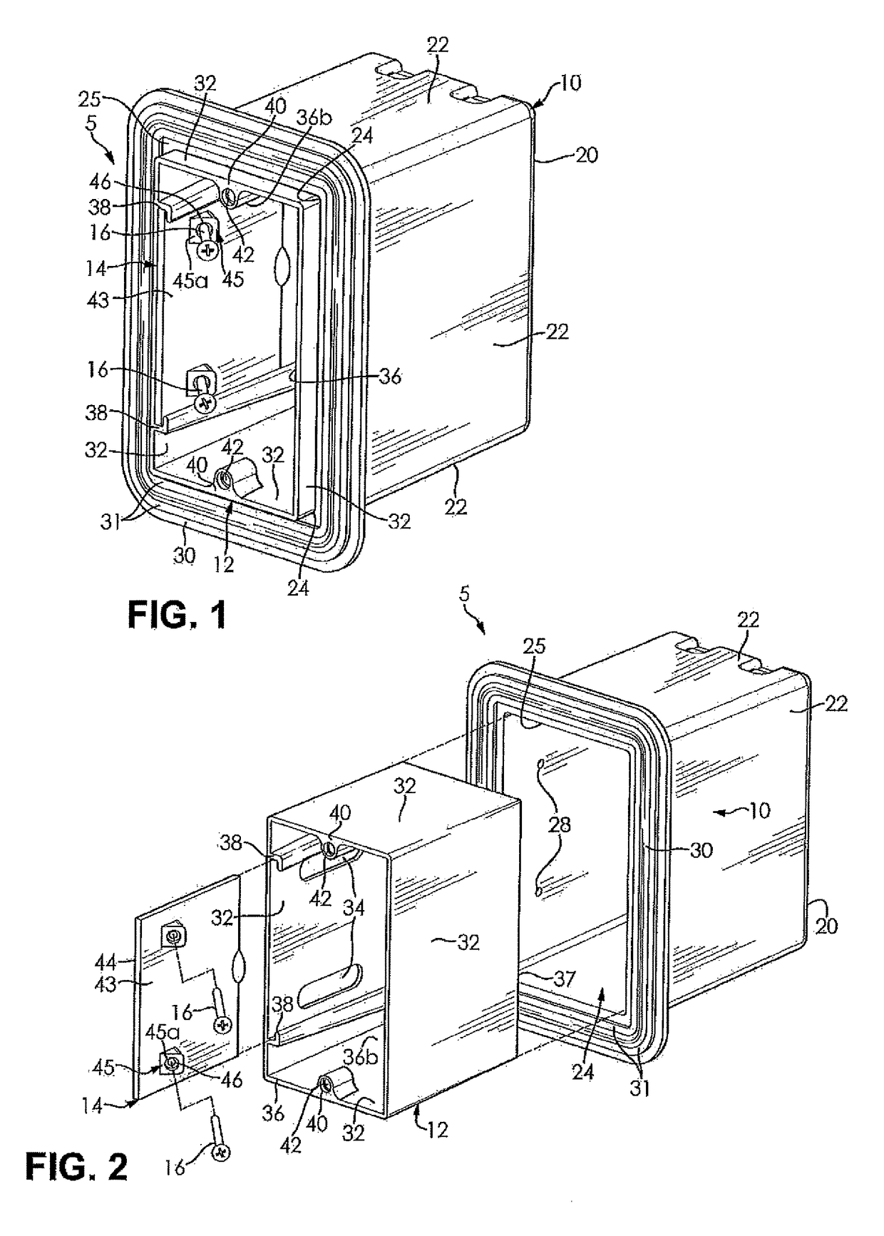
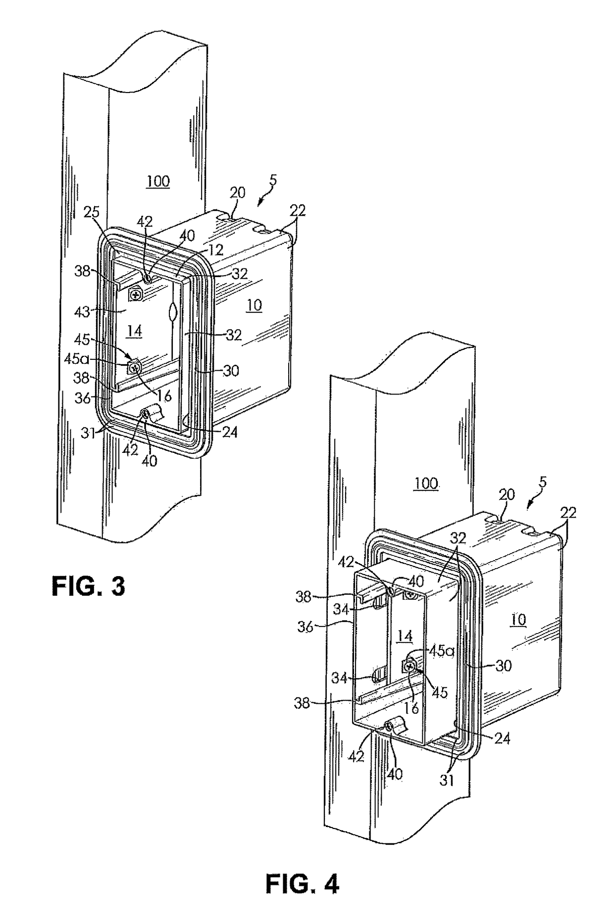
[0020]FIGS. 1-4 illustrate an electrical box assembly 5. The electrical box assembly 5 includes an outer box 10, a sleeve 12 slideably received within the outer box 10 and extendable in respect of the outer box 10, and a mounting plate 14 slidingly coupled to the sleeve 12. Mo...


PUM


Abstract

An electrical box assembly includes an outer box having a sidewall and a front opening. A sleeve having an inner surface is received in the front opening of the outer box and selectively extendable in respect of the outer box. A mounting plate is disposed on the inner surface of the sleeve. The mounting plate cooperates with the sleeve to selectively position the sleeve in respect of the outer box.

Description

CROSS-REFERENCE TO RELATED APPLICATIONS[0001]This patent application claims the benefit of U.S. Patent Provisional Application Ser. No. 62 / 090,392, filed on Dec. 11, 2014. The entire disclosure of the above patent application is hereby incorporated herein by reference.FIELD[0002]The present invention relates to an electrical box and more particularly to an electrical box having an adjustable sleeve that facilitates an extension of the electrical box while maintaining a vapor barrier in building construction.BACKGROUND OF THE INVENTION[0003]Typically, an electrical box is used to support and contain electrical devices and wiring in a centralized space. The electrical box protects the wiring and the electrical devices contained therein from extrinsic conditions. The electrical box is typically connected to a joist, a stud, or another structural component or surface of a building. A wall and / or ceiling substrate or membrane (such as drywall, for example) is secured to the structural co...

Claims


Application Information

Patent Timeline
Patent Type & Authority Patents(United States)
IPC IPC(8): H02G3/08
CPCH02G3/086
Inventor GENO, EVAN J.
Owner ALLIED MOLDED PRODS
Learn More