Driver apparatus provided with a motor and a control unit

a technology of control unit and drive shaft, which is applied in the direction of control/drive circuit, support/enclosement/case, dynamo-electric machines, etc., can solve the problems of difficult automation, time-consuming seal member attachment, and adverse effect of motor operation, so as to reduce the number of work steps

Active Publication Date: 2018-02-13
DENSO CORP
View PDF11 Cites 10 Cited by
  • Summary
  • Abstract
  • Description
  • Claims
  • Application Information

AI Technical Summary

Benefits of technology

[0007]It is an object of the present disclosure to provide a driver apparatus that enables a reduced number of work steps for an installation of a seal member that seals a through hole of the case, and that enables an automated installation of the seal member.
[0026]Therefore, when installing / assembling the seal member, the lead is inserted into the opening, while disposing the seal member to the case, which simplifies and reduces the number of work steps, which allows for the automation of such work steps.

Problems solved by technology

When such a structure is used, a foreign substance may enter the case from outside of the case through the through hole, thereby, causing an adverse effect on the operation of the motor.
Therefore, attachment of the seal member takes time and is difficult to automate.

Method used


Image

  • Driver apparatus provided with a motor and a control unit
  • Driver apparatus provided with a motor and a control unit
  • Driver apparatus provided with a motor and a control unit

Examples


Embodiment Construction

[0035]Hereafter, one embodiment of present disclosure is described based on the drawings.

One Embodiment

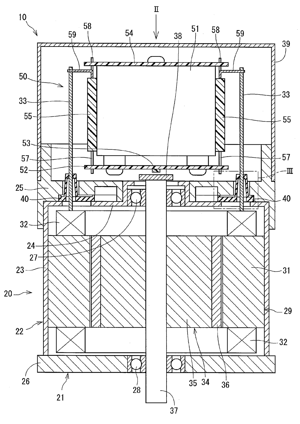
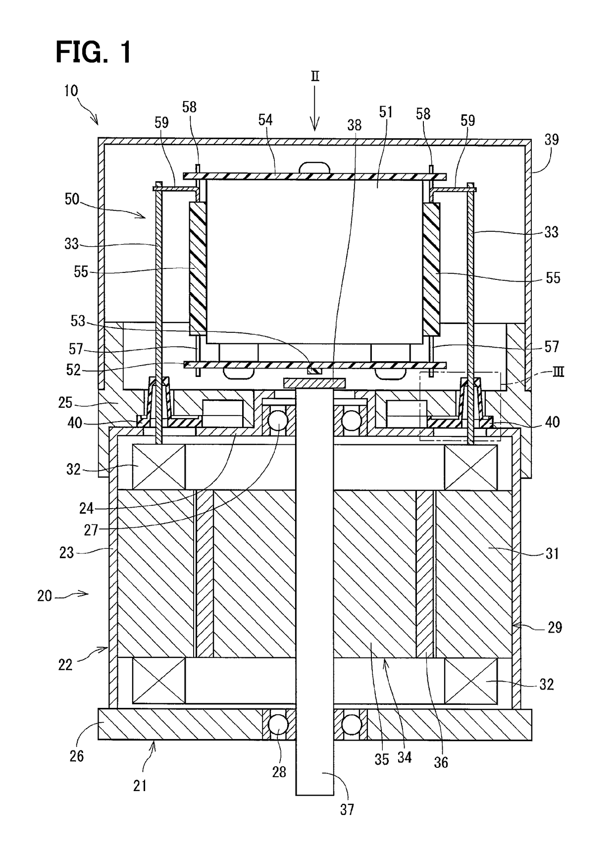
[0036]The driver apparatus in one embodiment of the present disclosure is used, for example, as a driving power source of an electric power steering device of the vehicles. As shown in FIG. 1, a driver apparatus 10 is a driver apparatus having one body structure that has a motor 20 and a controller 50 that controls the motor 20 in one body.

[0037][Entire Configuration]

[0038]First, an entire configuration of the driver apparatus 10 is described with reference to FIG. 1.

[0039](Motor)

[0040]The motor 20 is provided with a housing 21, a stator 29, a rotor 34, a revolving shaft 37, and a seal member 40. In the present embodiment, the motor 20 is a three-phase brushless motor.

[0041]The housing 21 comprises a case 22, a first frame end 25, and a second frame end 26. The case 22 has a cylinder shape with a bottom that closes one end of the cylinder shape, and includes a cylinder part 23 and ...


PUM


Abstract

A seal member of a driver apparatus contacts a case and a first frame end. The seal member has an opening in which a lead wire is inserted and an inside wall surface of the opening contacts the lead wire. Further, the seal member is made of a stretchable material, and is held in position only by a binding force between the case and the first frame end. The seal member is fixedly held by the first frame end and the case after an insertion of the lead wire in the opening and disposition on the fixing member opposing face. Therefore, an installation of the seal member is performed by an inserting the lead wire into the opening and a positioning the seal member on the case.

Description

CROSS REFERENCE TO RELATED APPLICATION[0001]The present application is based on and claims the benefit of priority of Japanese Patent Application No. 2014-016525, filed on Jan. 31, 2014, the disclosure of which is incorporated herein by reference.TECHNICAL FIELD[0002]The present disclosure generally relates to a driver apparatus provided with a motor and a control unit for controlling the motor.BACKGROUND INFORMATION[0003]In a motor having a stator and a rotor within a case, in order to connect a lead wire of a coil of the stator to an external control device, it is necessary for the lead wire to extend out of the case through a through hole of the case. When such a structure is used, a foreign substance may enter the case from outside of the case through the through hole, thereby, causing an adverse effect on the operation of the motor.[0004]In coping with such a situation, a patent document 1 (i.e., Japanese Patent Laid-Open No. H11-89156) discloses the following structure, in whi...

Claims


Application Information

Patent Timeline
Patent Type & Authority Patents(United States)
IPC IPC(8): H02K5/10H02K5/22H02K11/33
CPCH02K5/10H02K11/33H02K5/225
Inventor TOMIZAWA, HIROKITANIGUCHI, MAKOTOIMAI, HIROSHI
Owner DENSO CORP
Why Eureka
Try Eureka