Compressor

a compressor and rotor technology, applied in the field of compressors, can solve the problems of prolonging the life of the bearing assembly and thus the compressor, and achieve the effects of improving the electromagnetic and aerodynamic performance of the compressor, good alignment with the rotor assembly, and tight clearance or fi

Active Publication Date: 2018-02-20
DYSON TECH LTD
View PDF42 Cites 0 Cited by
  • Summary
  • Abstract
  • Description
  • Claims
  • Application Information

AI Technical Summary

Benefits of technology

[0005]The heat sink assembly acts to carry heat away from the bearing assembly. As a result, the lifespan of the bearing assembly and thus the compressor may be prolonged. The heat sink assembly is secured directly to the rotor assembly and to the stator assembly. Accordingly, the heat sink assembly may be used to achieve accurate alignment between the rotor assembly and the stator assembly. In particular, the rotor assembly and the stator assembly may be aligned and then the heat sink assembly may be secured to both assemblies so as to maintain the alignment. The collective subassembly (i.e. the rotor assembly, stator assembly and heat sink assembly) may then be secured within a frame of the compressor whilst maintaining the alignment between the rotor assembly and the stator assembly. With conventional compressors, the rotor assembly and the stator assembly are typically secured to the frame as separate assemblies. Owing to tolerances in the alignment of the rotor assembly and the stator assembly, a larger air gap is required between the rotor core and the stator cores in order to ensure that, at the tolerance limit, the rotor core is free to rotate without contacting the stator cores. By securing both the rotor assembly and the stator assembly to the heat sink assembly, and then securing the subassembly within the frame, a smaller air gap may be achieved between the rotor core and the stator assembly. Moreover, when securing the subassembly to the frame, the rotor assembly may be aligned relative to other components of the compressor (e.g. diffuser or shroud) whilst maintaining the alignment between the rotor assembly and the stator assembly. Accordingly, the electromagnetic performance of the compressor may be improved without sacrificing the aerodynamic performance.
[0025]The heat sink assembly is secured to the bearing assembly and then subsequently to the stator assembly. This then has the advantage that a relatively tight clearance or fit may be employed between the heat sink assembly and the bearing assembly. In spite of the tight clearance, movement of the stator assembly is unhindered and thus relatively good alignment with the rotor assembly may be achieved before securing the stator assembly to the heat sink assembly. By contrast, if the stator assembly were first secured to the heat sink assembly then, when securing the heat assembly to the rotor assembly, movement of the stator assembly relative to the rotor assembly would be limited due to the tight clearance between heat sink assembly and the rotor assembly, and thus the desired alignment may be difficult or impossible to achieve.

Problems solved by technology

As a result, the lifespan of the bearing assembly and thus the compressor may be prolonged.

Method used


Image

  • Compressor
  • Compressor
  • Compressor

Examples


Embodiment Construction

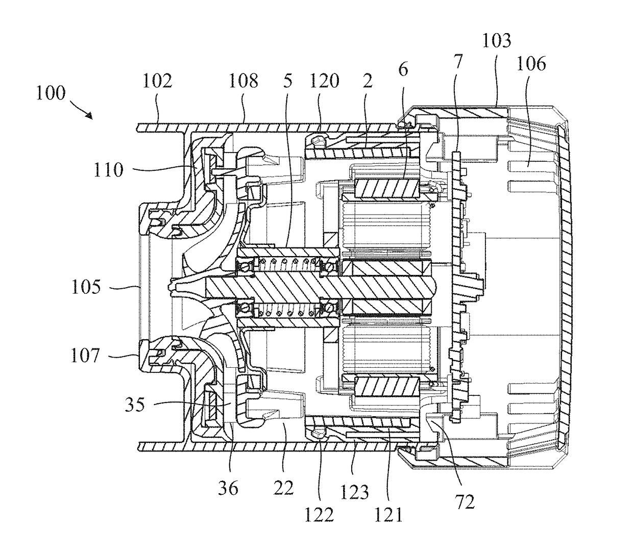
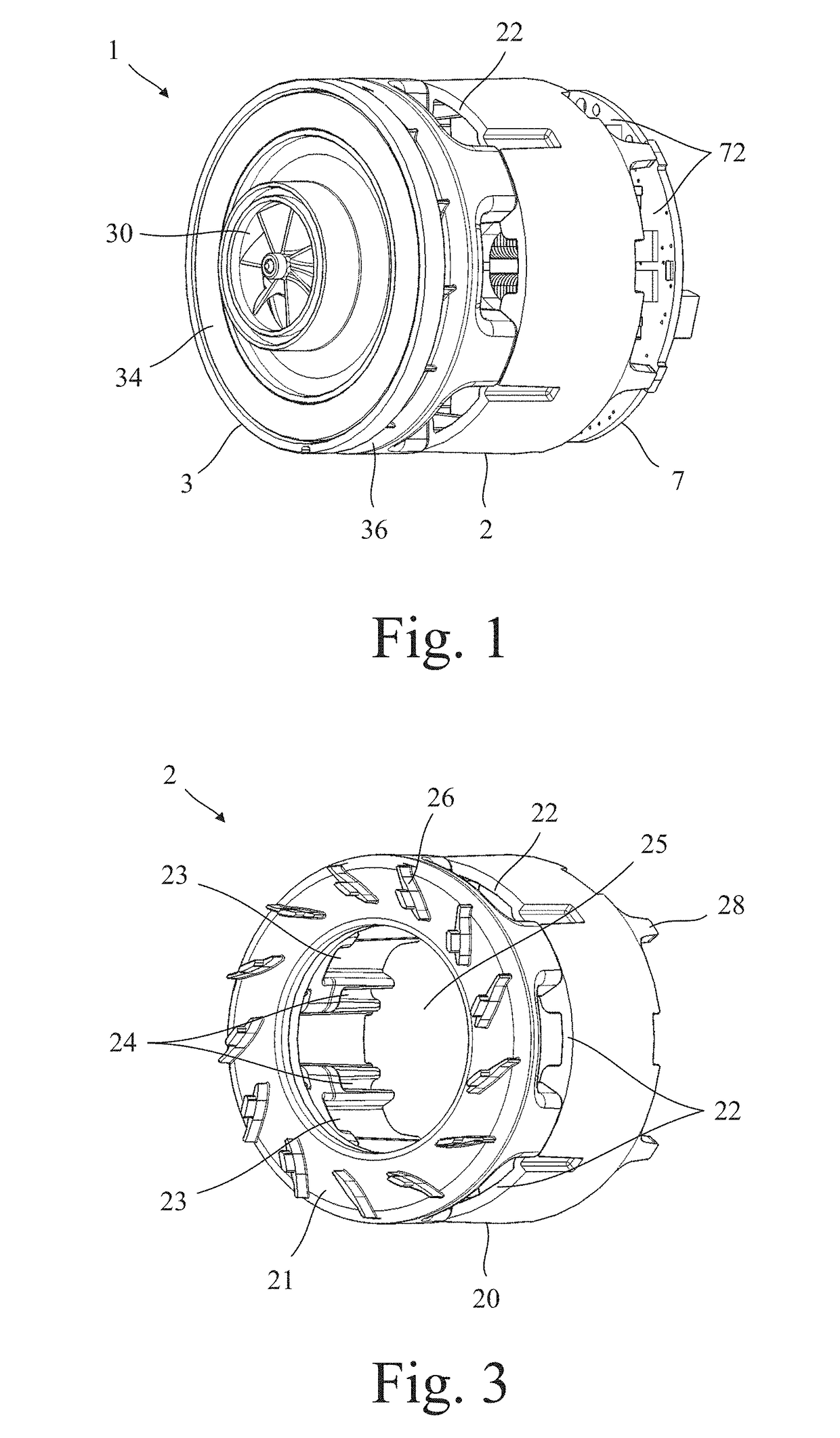
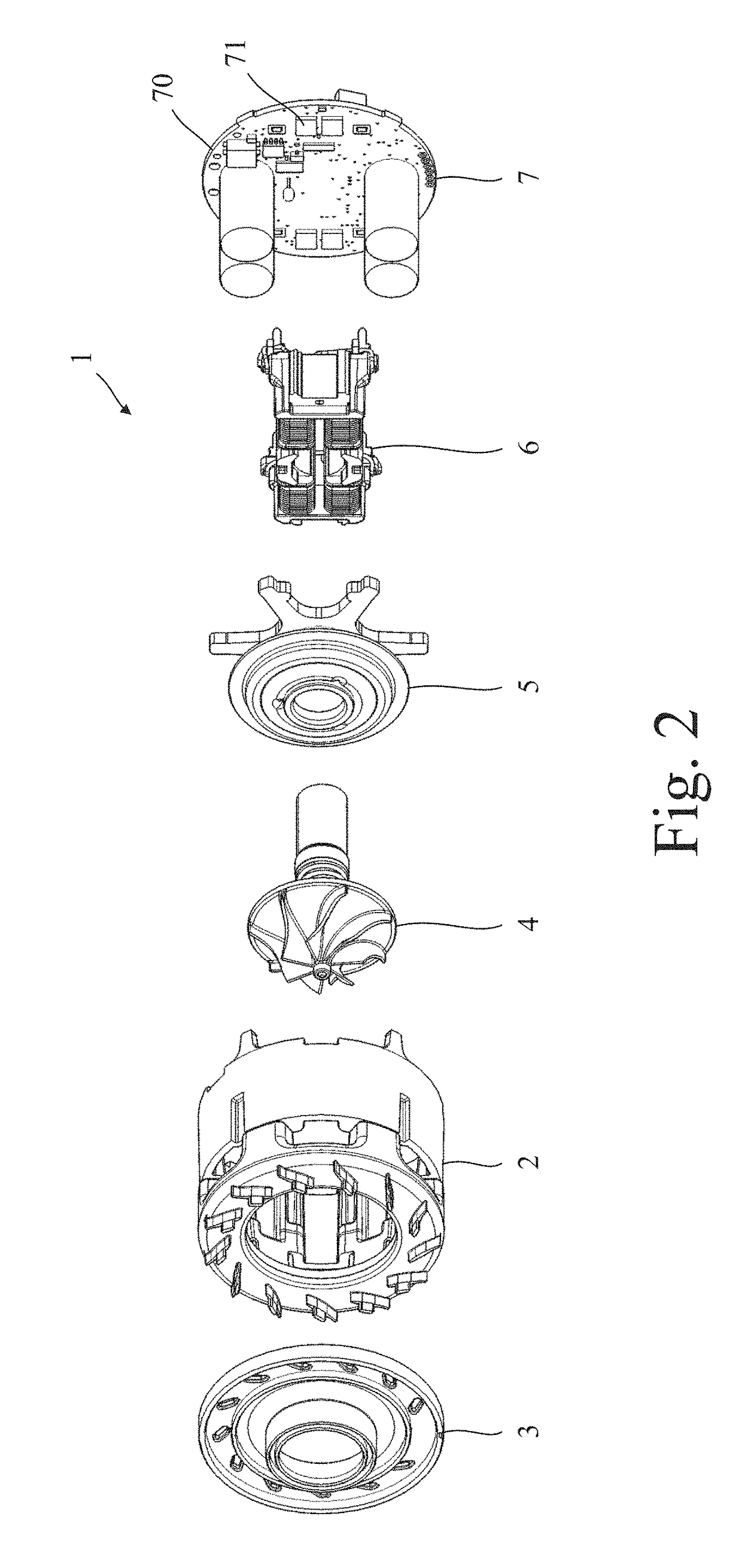
[0042]The compressor 1 of FIGS. 1 to 11 comprises a frame 2, a shroud 3, a rotor assembly 4, a heat sink assembly 5, a stator assembly 6, and a circuit assembly 7.

[0043]The frame 2 is generally cylindrical in shape and comprises a side wall 20, an end wall 21, a plurality of inlet apertures 22 located around the side wall 20, a plurality of pockets 23 and a plurality of channels 24 located on the inside of the side wall 20, a central aperture 25 located in the end wall 21, and a plurality of diffuser vanes 26 located around the end wall 21. The pockets 23 and the channels 24 take the form of recesses that extend axially along the inside of the side wall 20. The recesses are open at one end (distal the end wall 21) and closed at the opposite end (proximal the end wall 21). The end wall 21 is located at one end of the side wall 20 and resembles an annulus around which the diffuser vanes 26 are located. The opposite end of the side wall 20 is open and terminates with a plurality of pro...


PUM

PropertyMeasurementUnit
sizeaaaaaaaaaa
speedsaaaaaaaaaa
mass flow ratesaaaaaaaaaa

Abstract

A compressor that includes a rotor assembly, a stator assembly and a heat sink assembly. The rotor assembly includes a shaft to which a bearing assembly and a rotor core are secured. The heat sink assembly is then secured to the bearing assembly and to the stator assembly.

Description

REFERENCE TO RELATED APPLICATION[0001]This application claims priority of United Kingdom Application No. 1308093.2, filed May 3, 2013, the entire contents of which are incorporated herein by reference.FIELD OF THE INVENTION[0002]The present invention relates to a compressor.BACKGROUND OF THE INVENTION[0003]Efforts are continually being made to design compressors of smaller size. A smaller compressor may be achieved by employing a smaller impeller. However, a smaller impeller is required to rotate at higher speeds in order to achieve the same mass flow rates. Higher rotational speeds typically reduce the lifespan of the bearings, which are often the first components of the compressor to fail. Consequently, efforts to design a smaller compressor are often beset with lifespan problems.SUMMARY OF THE INVENTION[0004]The present invention provides a compressor comprising a rotor assembly, a stator assembly and a heat sink assembly, wherein the rotor assembly comprises a shaft to which a b...

Claims


Application Information

Patent Timeline
Patent Type & Authority Patents(United States)
IPC IPC(8): F04D29/58F04D29/62F16C41/00F04D29/059
CPCF04D29/5853F04D29/059F04D29/624F16C41/004F04D29/584Y10T29/49245F04D29/056F04D29/582F04D29/601
Inventor JACOB, PAUL ADRIAN GRAHAMKING, GARYLAKIN, DAVID FRANZ
Owner DYSON TECH LTD
Why Eureka
Try Eureka