Microfluidic disc for use in with bead-based immunoassays

a technology of microfluidic discs and immunoassays, applied in the field of microfluidic discs and apparatus, can solve the problems of large manual or robotic sample processing, high cost of manual processing, and easy errors, and achieve the effects of cost-prohibitive in many applications, and cost-prohibitive in automation

Active Publication Date: 2018-02-20
RADISENS DIAGNOSTICS
View PDF5 Cites 5 Cited by
  • Summary
  • Abstract
  • Description
  • Claims
  • Application Information

AI Technical Summary

Benefits of technology

[0035]The present invention provides a sheathless flow method appropriate for immunoassays which removes the complexity of sheath flow.
[0037]The invention also provides means for detection of beads in a flow-channel on the microfluidic disc while undergoing rotation. In one embodiment, the beads (or particles) are injected into the flow channel without the use of additional flow focusing due to sheaths, magnetism, inertial forces or other focusing means. This greatly simplifies the device architecture required to perform assays.
[0045]In other embodiments, sheath flow is employed. In these cases, simple 1-dimensional sheaths can be created using centrifugal force and easily-created microfluidic disc topologies, greatly decreasing the probability of multiple counting.

Problems solved by technology

One significant problem with currently implemented immunofluorescent bead assays is that they require extensive manual or robotic sample processing.
Manual processing is cost-prohibitive in many applications and is also prone to errors.
Automation is also cost-prohibitive in many applications, and is inappropriate as currently practiced—using, for example, liquid handling robots—for applications such as point-of-care or doctor's office analysis.
A drawback of Point-of-Care diagnostic assay systems is that they are typically incapable of multiplexing a variety of assay types.
While these systems are quite good at performing a variety of similar assay types—such as lateral flow assays, or electrochemical assays, etc.—the assay conditions required of different kinds of assays—such as immunoassay vs. colorimetric blood chemistry—make them inappropriate for multiplexing these different assay types.
A further significant problem of currently implemented immunofluorescent bead assays is that they are run on instruments developed for hematologic flow cytometry.
While these instruments are capable of performing these assays, they are both expensive and complex, requiring significant maintenance and calibration.
While this is very useful for hematologic assays, it does not confer any advantage for the detection of large numbers of essentially identical objects, such as fluorescent beads, and greatly complicates the functioning of the system.
US patent publication number US2004 / 096867, Anderson et al, describes a system with trapped beads that are “washed through”, one weakness with this US patent publication is that it does not provide a means for moving beads from one point to another, making single bead detection impossible.
A further weakness is that systems with trapped beads forming the solid phase require manufacturing techniques that are demanding.
For example, in order to provide highly reproducible binding of analyte molecules and fluorescent labels, the packed ‘bed” of beads must be reproducibly structured; poor packing of the beads can lead to channels within the bead bed that pass analyte rapidly, without sufficient time for binding, resulting in low binding efficiency.
This temperature-sensitivity also makes storage of enzyme-based reagents for long periods (long shelf life) difficult.
There are several problems to this formatting of an affinity method.
In each case, manufacturing requirements are significant, requiring specialized methods for the production of features as low as a few to a few tens of microns.

Method used


Image

  • Microfluidic disc for use in with bead-based immunoassays
  • Microfluidic disc for use in with bead-based immunoassays
  • Microfluidic disc for use in with bead-based immunoassays

Examples


embodiments

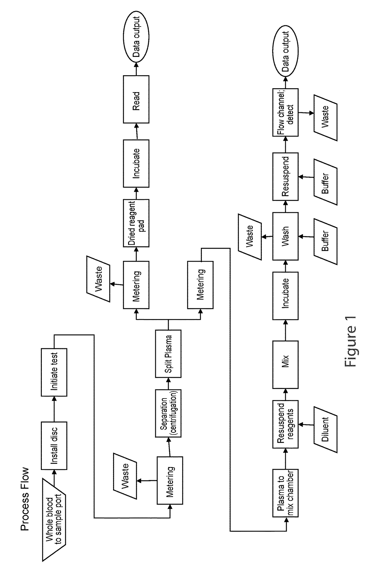
[0178]Many forms of immunoassay for a centrifugal format with flowing beads as the detection step can be implemented incorporating the invention. For example in one embodiment:[0179]1. Mix 50 uL functionalized beads (6000 beads) with 50 uL of sample and 50 uL labeling reagent (phycoerythrin, PE) (VS=150 uL)[0180]2. Incubate 3 hours[0181]3. Add 1000 uL wash buffer (VW)[0182]4. Centrifuge to pellet beads[0183]5. Discard supernatant[0184]6. Resuspend in 300 uL of buffer (VE)[0185]7. Perform flow cytometry

[0186]Fundamentally, bead washing is removal of excess of unincorporated dye (PE) to a level where it does not interfere with detection of bead fluorescence (i.e., the background is low relative to the bead fluorescence).

[0187]Embodiments of Washing

[0188]Preferred embodiments of washing include:[0189]Pellet+decant+dilute: Centrifugation to pellet beads; remove (decant) supernatant, leaving behind a residual amount of solution; and resuspension of beads in buffer to achieve sufficient r...

examples

[0310]A possible construction of microfluidic discs according to the invention is shown in FIG. 15. This microfluidic disc consists of three main components: A fluidic layer 100 which contains the majority of fluidic structures such as reservoirs, channels, passive valves, and reagents in the form of liquid reagents or dried reagents; a thin interlayer 200 containing primarily through holes; and a lower or channel layer 300. Communication between 100 and 300 is via the through holes in 200. Such a construction is useful when making three-dimensional architectures requiring liquid ‘crossovers’, in which channels must pass over one another.

[0311]It is recognized that this construction is in no way limiting. Microfluidic discs may be formed by sealing a fluidic layer with an essentially featureless layer or thin film, without additional channels or through holes. In one construction there is provided a featureless sealing film and a disc.

[0312]Immunoassay and Clinical Chemistry Device

[...


PUM

PropertyMeasurementUnit
sizeaaaaaaaaaa
widthaaaaaaaaaa
accelerationaaaaaaaaaa

Abstract

The invention relates to a microfluidic system for processing biological samples comprising a rotary motor; a means for controlling said motor; a platform coupled to the rotary motor and adapted to provide at least one particle-washing structure and one particle receiving structure for receiving washed particles; and a detection zone for detection of particles of the sample in the particle receiving structure while the platform rotates. The invention provides a sample processing system that is both automated and prone to fewer errors than manual processing. This is accomplished using a centrifugal microfluidic platform that can process raw biological samples (e.g., blood, sputum, urine,) in order to perform high-quality bead-based immunofluorescent assays. The invention uses a simple rotary motor and custom-designed plastic disc to perform the sample preparation steps outlined above.

Description

CROSS REFERENCE RELATED APPLICATIONS[0001]This application is a national phase under 35 U.S.C. § 371 of International Application No. PCT / IE2012 / 000026 filed on Jun. 5, 2012, which claims the benefit of and priority to European Patent Application 11168702.6 and U.S. Provisional application 61 / 493,234 both filed on Jun. 3, 2011, the entire disclosures of each of which are incorporated herein by reference.FIELD OF THE INVENTION[0002]The invention relates to a microfluidic disc, apparatus, system and method, for use in immunoassay diagnostics or in a portable diagnostic analyser.BACKGROUND TO THE INVENTION[0003]Flow cytometry is a powerful method of analysis to determine the cellular / biological content of various types of samples, and in particular samples that contain living cells. In clinical applications, flow cytometers are useful for myriad of applications including lymphocyte counting and classification, for immunological characterization of leukaemias and lymphomas, leukocyte co...

Claims


Application Information

Patent Timeline
Patent Type & Authority Patents(United States)
IPC IPC(8): B01L3/00G01N33/53G01N33/543
CPCB01L3/502753G01N33/5304G01N33/543G01N33/54366B01L2200/0652B01L2200/0684B01L2300/0681B01L2300/0803B01L2400/043B01L2400/0409B01L2400/0677B01L2400/0688B01L2400/086B01L2400/088B01L2200/0636G01N35/00
Inventor KELLOGG, GREGO'BRIEN, JERRYO'NUALLAIN, EOINCURTIN, DAMIAN
Owner RADISENS DIAGNOSTICS
Why Eureka
Try Eureka