

Method for direct screwing of structural components, in particular for flow hole screwing and device for direct screwing of structural components
- Summary
- Abstract
- Description
- Claims
- Application Information
AI Technical Summary
Benefits of technology
Problems solved by technology
Method used
Image

Examples
Embodiment Construction
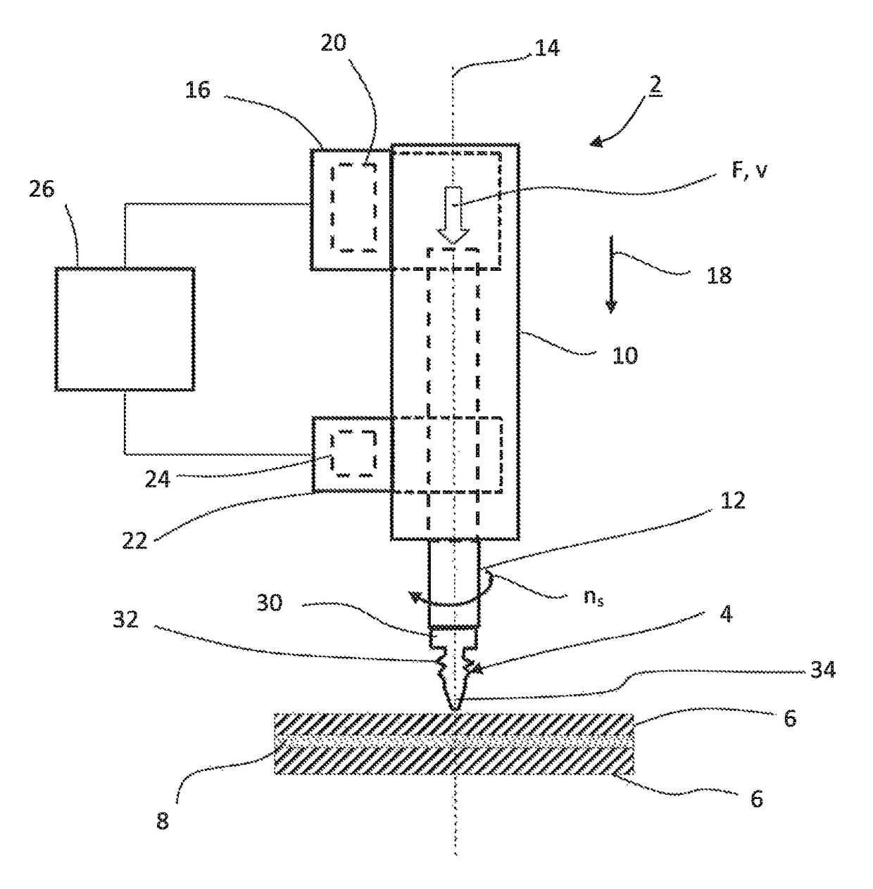
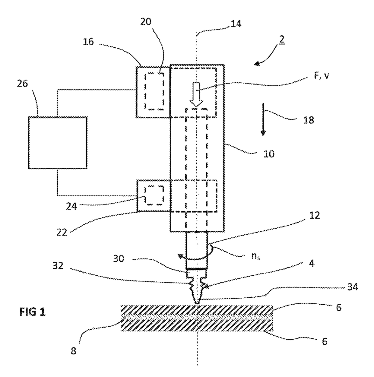
[0040]The device 2 illustrated in FIG. 1 is used to carry out a flow hole screwing procedure. During this procedure what is known as a flow hole screw 4 is inserted into at least one structural component 6. In the exemplary embodiment two structural components 6 to be connected to one another via the flow hole screw 4 are illustrated and are connected to one another additionally via an adhesive layer 8.
[0041]The device 2 comprises a holder 10, which for example is formed in the manner of a housing. A screw shaft 12 is mounted rotatably about an axis of rotation 14 within the holder 10. The device 2 also comprises a feed drive 16 for generating a feed movement in the axial direction 18 and also for generating a feed force F. The feed force F and the feed movement are transmitted here to the screw shaft 12. A feed rate v is transmitted to the screw shaft 12 via the feed drive 16 and is thus used to move the screw shaft in the axial direction 18.
[0042]The feed drive 16 has a first elec...
PUM
| Property | Measurement | Unit |
|---|---|---|
| Force | aaaaa | aaaaa |
| Force | aaaaa | aaaaa |
| Angular velocity | aaaaa | aaaaa |
Abstract
Description
Claims
Application Information