Ultra thin display module and method for assembling the same

a display module and ultra-thin technology, applied in non-linear optics, instruments, optics, etc., can solve the problems of insufficient thickness of display modules and limit the thickness of those components, and achieve the effect of greatly reducing the thickness of the modules

Active Publication Date: 2018-02-27
TCL CHINA STAR OPTOELECTRONICS TECH CO LTD
View PDF4 Cites 0 Cited by
  • Summary
  • Abstract
  • Description
  • Claims
  • Application Information

AI Technical Summary

Benefits of technology

[0005]In view of the above problems, the disclosure provides an ultra thin display module and a method for assembling the same such that the thickness of the module is greatly decreased.
[0020]According to the disclosure, the ultra thin display module and method for assembling the same of the disclosure use a brand new structure of ultra thin display module, such that the thickness of the module is greatly decreased as compared with the present techniques.

Problems solved by technology

However, there are limits for the thickness of those components, such that there is a minimum thickness of the display module, and the thickness of the display modules are not thin enough.

Method used


Image

  • Ultra thin display module and method for assembling the same
  • Ultra thin display module and method for assembling the same
  • Ultra thin display module and method for assembling the same

Examples


embodiment 1

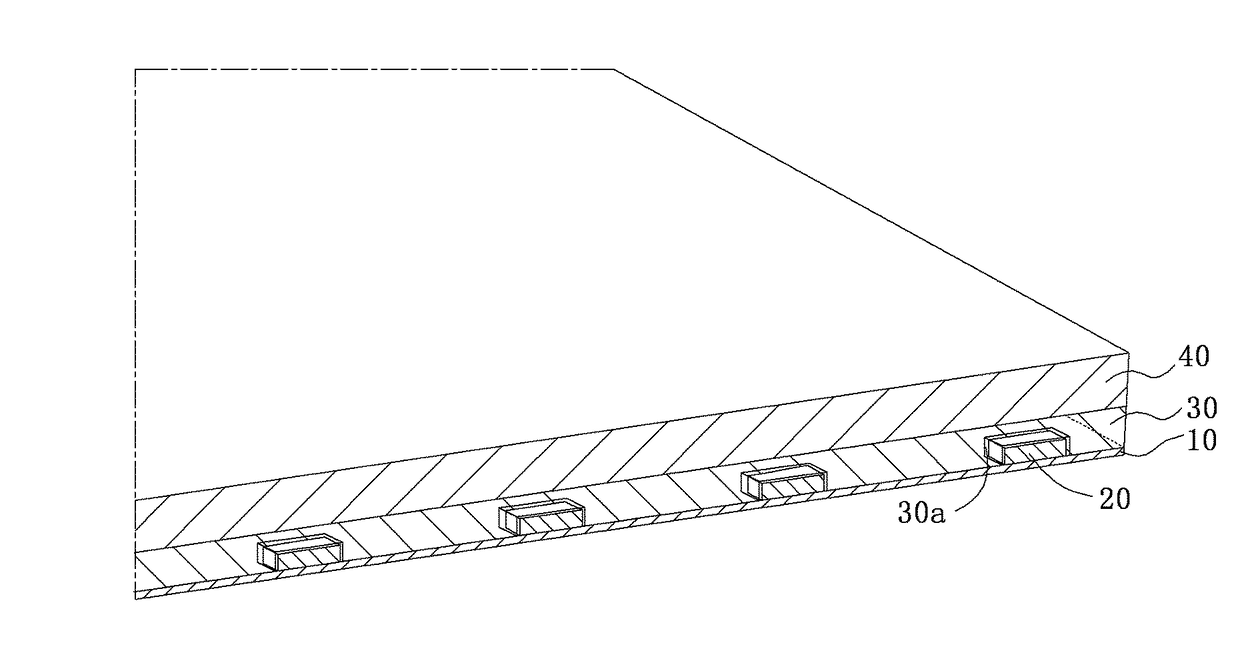
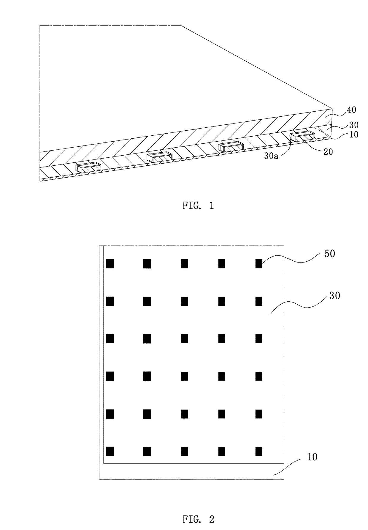
[0027]Refer to FIGS. 1-2, the ultra thin display module of the disclosure comprises a LED substrate 10, a plurality of LED lamp beads 20, a secondary lens 30 and a display panel 40. The plurality of LED lamp beads 20 is disposed on the array of the LED substrate 10, the secondary lens 30 is disposed on the LED substrate 10, the secondary lens 30 is encapsuled inside the top surface of the LED lamp beads 20, and the display panel 40 is disposed on the top surface of the secondary lens 30.

[0028]As compared with the structure of traditional display modules, iron frames, reflective sheets, light guiding plates and optical films are eliminated, so that the display module of the disclosure only comprises a LED substrate 10, a secondary lens 30 and a display panel 40 along the direction of the thickness of the structure, such that the thickness of the display module is greatly decreased and the display module is significantly thin.

[0029]The surface of the top of the secondary lens 30 is co...

embodiment 2

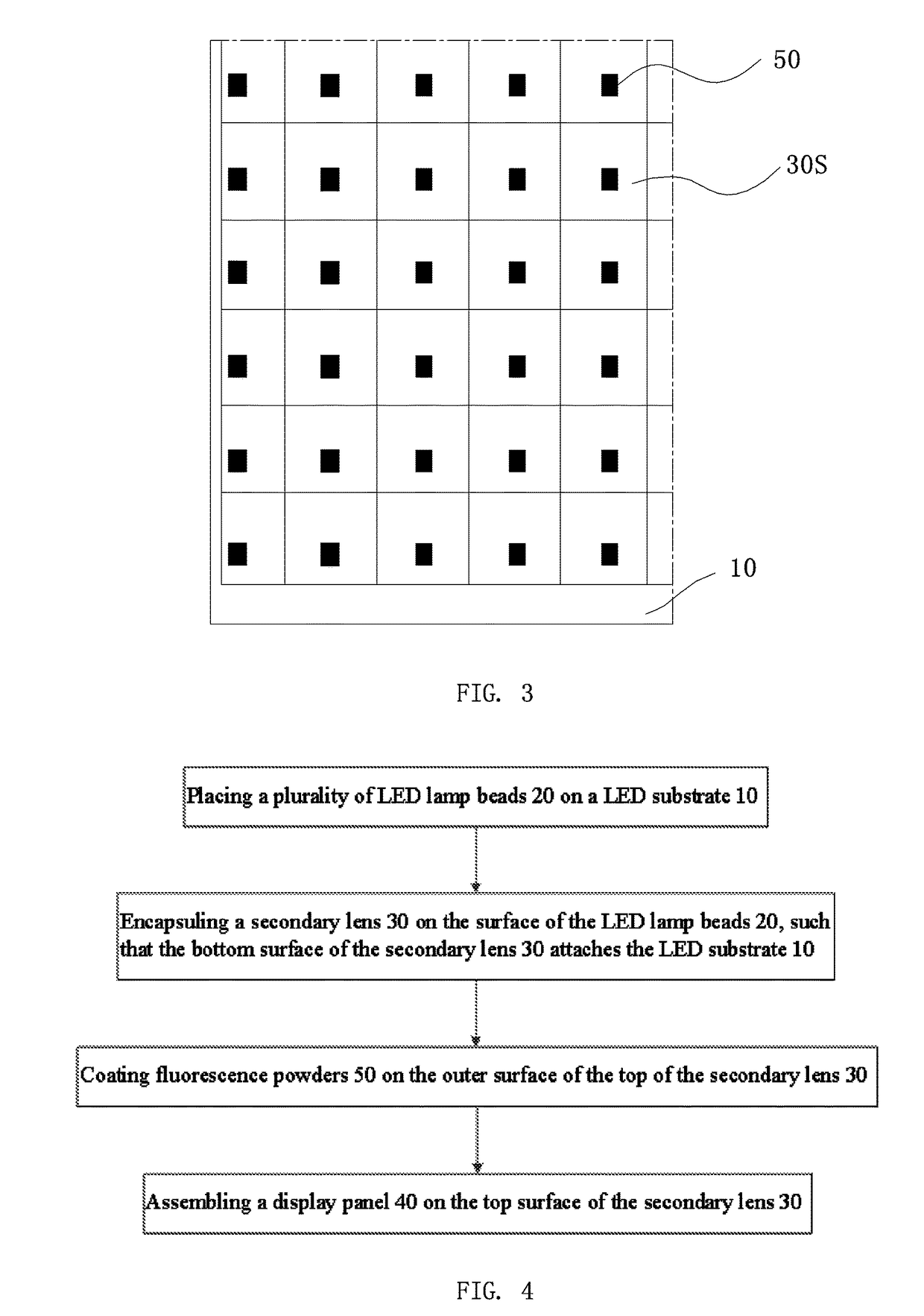
[0031]As shown in FIG. 3, the difference between Embodiment 2 and Embodiment 1 is that the secondary lens 30 of the embodiment is assembled by a plurality of lens units 30S. The plurality of lens units 30 is rectangular. Each of the inner surface of the plurality of lens units 30S has a groove 30a, the LED lamp beads 20 are embedded into the grooves 30a, and the plurality of lens units 30S is assembled together closely. The fluorescence powders 50 are coated on the inner surface of the grooves 30a.

embodiment 3

[0032]As shown in FIG. 4, the embodiment provides a method for assembling an ultra thin display module, comprising: placing a plurality of LED lamp beads 20 on a LED substrate 10; encapsuling a secondary lens 30 on the surface of the LED lamp beads 20, such that the bottom surface of the secondary lens 30 attaches the LED substrate 10; and assembling a display panel 40 on the top surface of the secondary lens 30.

[0033]Wherein, before the step of assembling a display panel 40 on the top surface of the secondary lens 30, the method further comprises the step of coating fluorescence powders 50 on the outer surface of the top of the secondary lens 30. Alternatively, the method further comprises the step of coating fluorescence powders 50 on the inner surface of the inner surface of the secondary lens 30, which is opposite to the LED lamp beads 20.

[0034]Wherein, the secondary lens 30 is integrally formed. Before the step of encapsuling a secondary lens 30 on the surface of the LED lamp b...


PUM

PropertyMeasurementUnit
fluorescenceaaaaaaaaaa
thicknessaaaaaaaaaa

Abstract

The disclosure provides an ultra thin display module, comprising a LED substrate, a plurality of LED lamp beads, a secondary lens and a display panel. The plurality of LED lamp beads is disposed on the array of the LED substrate, the secondary lens is disposed on the LED substrate, the secondary lens is encapsuled inside the top surface of the LED lamp beads, and the display panel is disposed on the top surface of the secondary lens. The ultra thin display module and method for assembling the same of the disclosure use a brand new structure of ultra thin display module, such that the thickness of the module is greatly decreased as compared with the present techniques.

Description

BACKGROUND OF THE INVENTION[0001]1. Field of the Invention[0002]The disclosure relates to the liquid crystal display field, and more particularly, to an ultra thin display module and a method for assembling the same.[0003]2. The Related Arts[0004]Accompanied with the development of the liquid crystal techniques, it is more and more important to decrease the thickness of the products. At present, display modules are assembled by display panels and backlight modules. The thickness of the display modules is decreased by thinning the backlight module. Currently, the backlight module is constituted by iron frames, reflective sheets, backlight plates and optical films. Thus, the thickness of the display modules is decreased by thinning the components in the backlight modules. However, there are limits for the thickness of those components, such that there is a minimum thickness of the display module, and the thickness of the display modules are not thin enough.SUMMARY[0005]In view of the ...

Claims


Application Information

Patent Timeline
Patent Type & Authority Patents(United States)
IPC IPC(8): G02F1/1335
CPCG02F1/133603G02F2001/133607G02F1/133607
Inventor ZHANG, YANXUE
Owner TCL CHINA STAR OPTOELECTRONICS TECH CO LTD
Why Eureka
Try Eureka