
Fingerprint sensor and display device including the same

a fingerprint sensor and display device technology, applied in the field of fingerprint sensors and display devices, can solve the problems of increased manufacturing cost and increased thickness of display devices, and achieve the effect of reducing the thickness of modules and improving reliability

Active Publication Date: 2021-11-23
SAMSUNG DISPLAY CO LTD
View PDF17 Cites 0 Cited by
  • Summary
  • Abstract
  • Description
  • Claims
  • Application Information

AI Technical Summary

Benefits of technology

[0006]Devices constructed according to exemplary embodiments of the invention are capable of providing a fingerprint sensor using a light sensing method that is capable of reducing a thickness of a module and improving reliability, and a display device including the fingerprint sensor.
[0007]In addition, devices constructed according to exemplary embodiments of the invention are capable of providing a fingerprint sensor capable of minimizing incident light diffraction at an edge of an opening portion provided for controlling incident light in a display panel, and a display device including the fingerprint sensor.
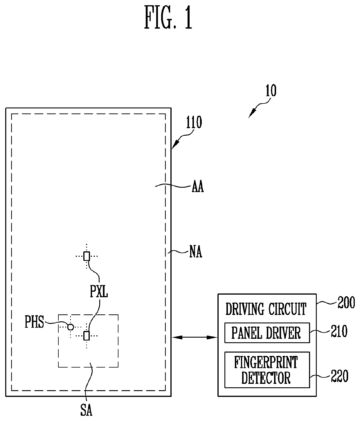
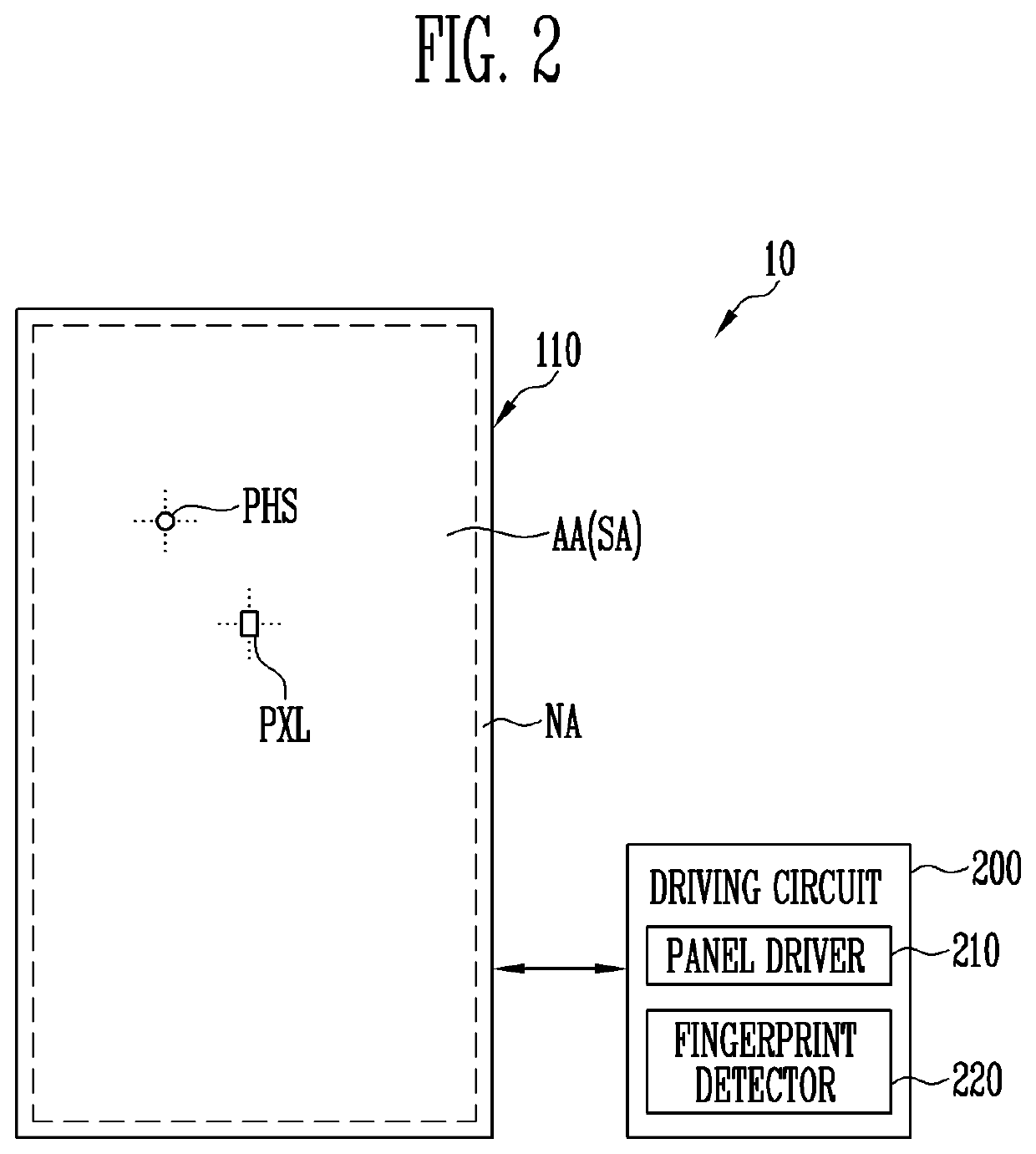
[0029]The fingerprint sensor and the display device including the same according to exemplary embodiments of the inventive concepts may reduce a module thickness of the display device by forming a light transmission area integrally with the circuit element layer in the fingerprint sensor for the light sensing method.
[0030]In addition, the fingerprint sensor and the display device including the same according to exemplary embodiments of the inventive concepts may prevent or reduce diffraction of light that may occur in the light transmission area formed in the circuit element layer.

Problems solved by technology

When such a fingerprint sensor is attached to a display panel, a thickness of the display device may increase and a manufacturing cost may increase.

Method used


Image

  • Fingerprint sensor and display device including the same
  • Fingerprint sensor and display device including the same
  • Fingerprint sensor and display device including the same

Examples


Embodiment Construction

[0049]In the following description, for the purposes of explanation, numerous specific details are set forth in order to provide a thorough understanding of various exemplary embodiments or implementations of the invention. As used herein “embodiments” and “implementations” are interchangeable words that are non-limiting examples of devices or methods employing one or more of the inventive concepts disclosed herein. It is apparent, however, that various exemplary embodiments may be practiced without these specific details or with one or more equivalent arrangements. In other instances, well-known structures and devices are shown in block diagram form in order to avoid unnecessarily obscuring various exemplary embodiments. Further, various exemplary embodiments may be different, but do not have to be exclusive. For example, specific shapes, configurations, and characteristics of an exemplary embodiment may be used or implemented in another exemplary embodiment without departing from ...


PUM

PropertyMeasurementUnit
angleaaaaaaaaaa
angleaaaaaaaaaa
widthaaaaaaaaaa

Abstract

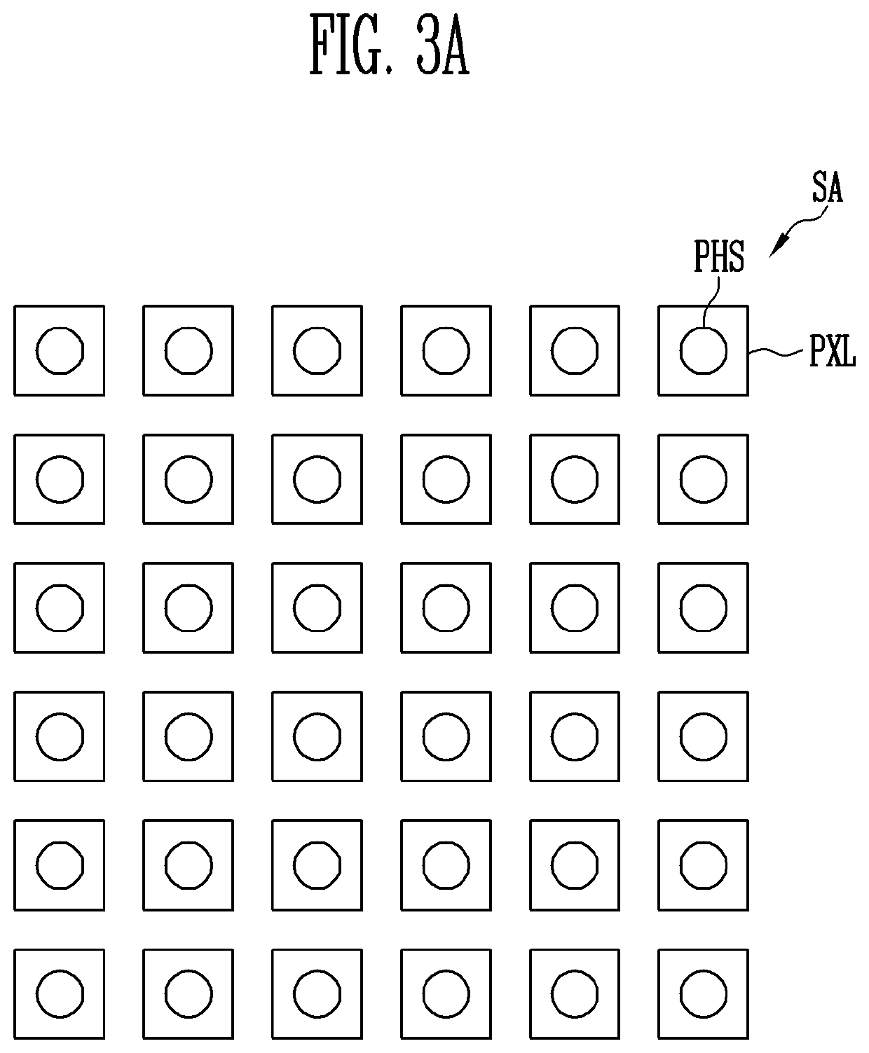
A fingerprint sensor and a display device include a substrate. A circuit element layer is disposed on a first surface of the substrate and includes a semiconductor layer, conductive layers and at least one opening portion. A light emitting element layer is disposed on the circuit element layer and includes at least one light emitting element. A sensor layer is disposed on a second surface of the substrate and includes at least one light sensor corresponding to the opening portion. The opening portion is defined by non-overlapping of the semiconductor layer and the conductive layers, the opening portion has a closed loop shape in plan view, and at least a portion of the closed loop shape includes a curve, or an internal angle of the at least a portion of the closed loop shape is an obtuse angle.

Description

CROSS REFERENCE TO RELATED APPLICATION[0001]This application claims priority from and the benefit of Korean Patent Application No. 10-2019-0119017, filed on Sep. 26, 2019, which is hereby incorporated by reference for all purposes as if fully set forth herein.BACKGROUNDField[0002]Exemplary embodiments of the invention relate generally to a fingerprint sensor and a display device including the same.Discussion of the Background[0003]In recent years, as a display device such as a smartphone or a tablet PC has been widely used, a biometric information authentication method using a fingerprint of a user has been widely used. In order to provide a fingerprint sensing function, a fingerprint sensor may be provided in a form embedded or attached to a display device.[0004]For example, the fingerprint sensor may be configured with a sensor using a light sensing method. The fingerprint sensor for the light sensing method may include a light source, a lens, and a light sensor array. When such a...

Claims


Application Information

Patent Timeline
Patent Type & Authority Patents(United States)
IPC IPC(8): G06K9/00H01L27/32
CPCG06K9/0004G06K9/00053H01L27/323H01L27/14678G06V40/1324G06V40/1318H10K59/65G06F3/041H01L27/1214H10K59/40G06V40/1329
Inventor LEE, SUN HWALEE, KI JUNEJEON, MU KYUNG
Owner SAMSUNG DISPLAY CO LTD
Learn More