Aircraft and particulate detection method

a technology for aircraft and particulates, applied in the direction of combustion-air/fuel-air treatment, machines/engines, instruments, etc., can solve the problems of negative affecting engine performance and subsequent overhaul cos

Active Publication Date: 2018-03-06
GE AVIATION SYST LLC
View PDF30 Cites 10 Cited by
  • Summary
  • Abstract
  • Description
  • Claims
  • Application Information

AI Technical Summary

Problems solved by technology

Such engines may ingest various types of particulate matter such as ash, sand, dust, dirt, gravel, and pollutants, which may negatively affect engine performance, the time the engine is on the wing of the aircraft (TOW), and subsequent overhaul cost.

Method used


Image

  • Aircraft and particulate detection method
  • Aircraft and particulate detection method
  • Aircraft and particulate detection method

Examples


Embodiment Construction

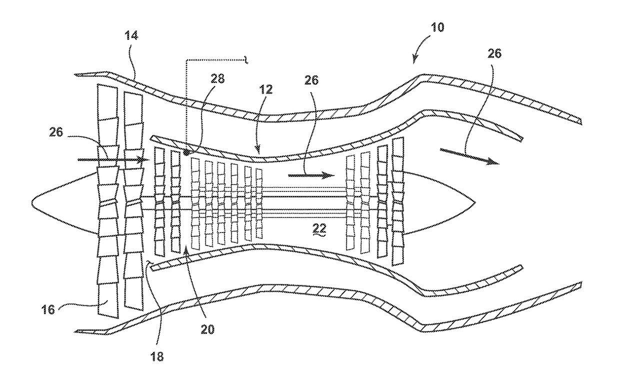
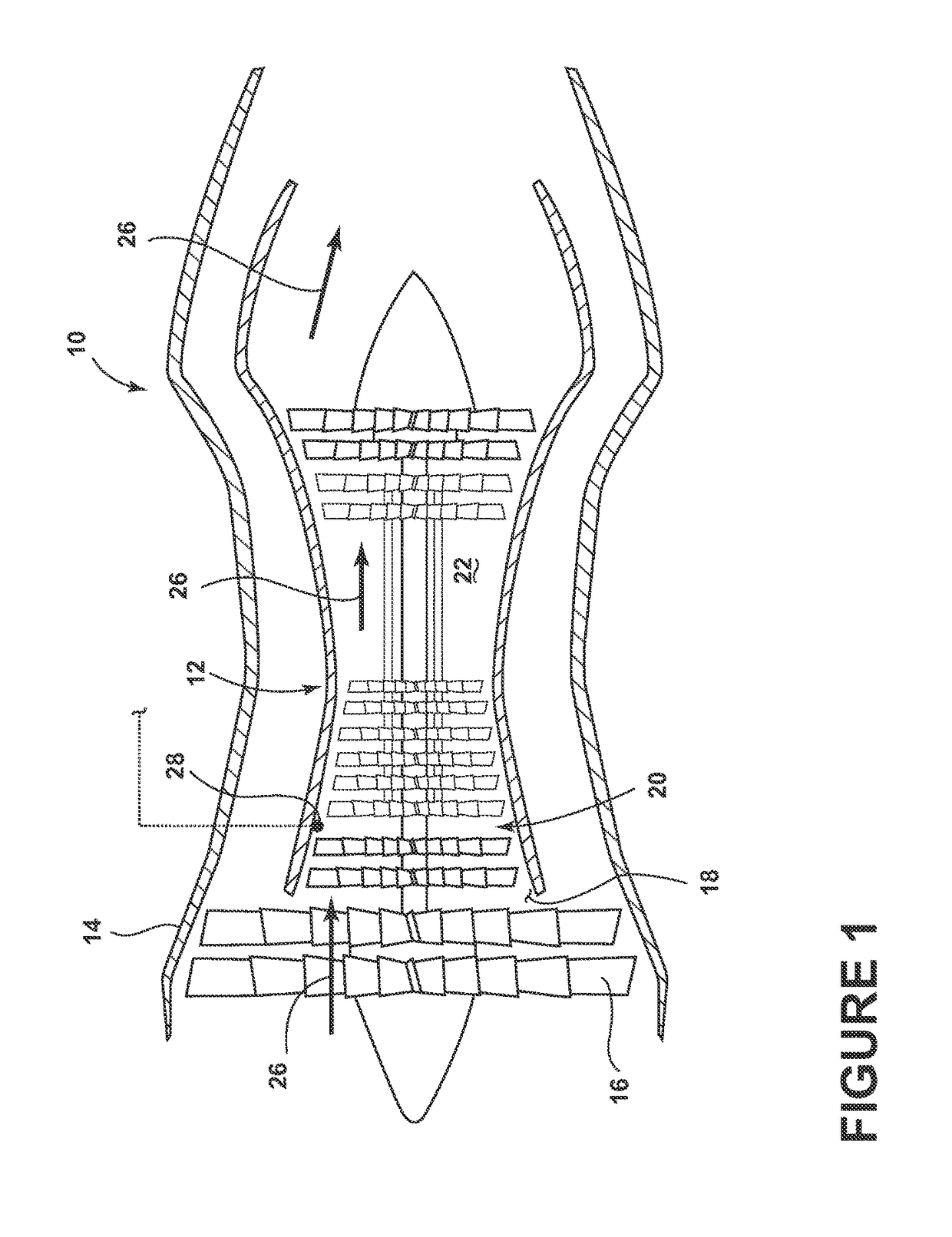
[0008]FIG. 1 schematically depicts a jet engine assembly 10 having a core 12, portions of which may be surrounded by a nacelle 14. The core 12 does not include the nacelle 14 and fan 16 of the jet engine assembly 10. The core 12 may include, among other things, an air intake 18, a compressor 20, and a combustion chamber 22 downstream from the compressor 20. Air may enter the air intake 18 and may be compressed in the compressor 20. Air may then be forced into the combustion chamber 22 where fuel is sprayed into it and the mixture of air and fuel may be ignited. Gases that form expand rapidly and are exhausted through the rear of the combustion chamber 22. Such an engine flow path is illustrated with arrows 26.

[0009]A particulate sensor 28 may be located within the core 12 and may be configured to output a signal indicative of sensed particles or particulates in a limited portion of the core 12. The particulate sensor 28 may be located within any suitable part of the core 12 in the e...


PUM

PropertyMeasurementUnit
altitudeaaaaaaaaaa
comparison thresholdaaaaaaaaaa
concentrationsaaaaaaaaaa

Abstract

An aircraft including a jet engine including a core having a compressor and combustion chamber, and a particulate sensor located within the core and a particulate detection method for an aircraft having a jet engine where the method includes sensing particulates within the core and providing a corresponding value for the sensed particulates and providing an indication related thereto.

Description

BACKGROUND[0001]Contemporary aircraft may include engines to provide propulsion for the aircraft. Such engines may ingest various types of particulate matter such as ash, sand, dust, dirt, gravel, and pollutants, which may negatively affect engine performance, the time the engine is on the wing of the aircraft (TOW), and subsequent overhaul cost. Harsh environments of the Middle East, Africa, India, and China, for example, can have a significant impact on engine TOW and hardware scrap / repair rates.BRIEF DESCRIPTION[0002]Embodiments of the innovation relate to a particulate detection method for an aircraft having a jet engine comprising a core, the method includes sensing particulates ingested into the core and providing a corresponding particulate value for the sensed particulates, selecting a particulate reference value, comparing the particulate value to the particulate reference value, and providing an indication based on the comparison.[0003]In another aspect, an embodiment of t...

Claims


Application Information

Patent Timeline
Patent Type & Authority Patents(United States)
IPC IPC(8): G01N15/10G01N15/06G01C21/20B64D45/00F02C7/05G01N15/00
CPCG01N15/0656B64D45/00F02C7/05G01C21/20G01N15/06G01N2015/0046B64D2045/009B64D2045/0085F05D2260/80
Inventor KNOBLOCH, AARON JAYKESSIE, ANDREW SCOTTSTEFFLER, JOSEPH BERNARDLOYAL, BRIAN JACOB
Owner GE AVIATION SYST LLC
Why Eureka
Try Eureka