
Main seal for a heavy-duty vehicle wheel end assembly

a technology for heavy-duty vehicles and wheel end assemblies, which is applied in the direction of hubs, mechanical devices, transportation and packaging, etc., can solve the problems of reducing the life affecting the performance of the wheel end assembly, and prior art contact-type seals lacking enhanced combinations of contaminant-exclusion features, so as to achieve the effect of increasing contaminant exclusion

Active Publication Date: 2018-03-13
TENNECO INC +1
View PDF24 Cites 9 Cited by
  • Summary
  • Abstract
  • Description
  • Claims
  • Application Information

AI Technical Summary

Benefits of technology

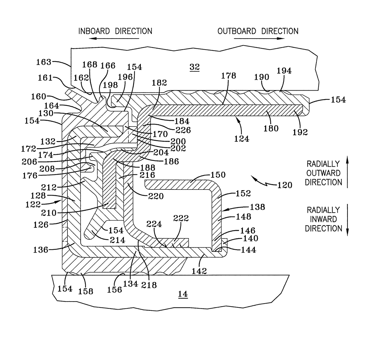
The present invention provides an improved main seal for a heavy-duty wheel end assembly. The main seal has increased contaminant exclusion and minimal drag to preserve its life and optimize fuel efficiency. The main seal includes a dynamic portion and a static portion, with an elastomer bonded to a rigid carrier and forming a first external lip that prevents contaminants from entering the wheel end assembly.

Problems solved by technology

Therefore, the wheel end assembly must be sealed to prevent leakage of the lubricant, and also to prevent contaminants from entering the assembly, both of which could be detrimental to its performance.
However, while often desirably reducing drag, the non-contact nature of the components of such seals have not optimized the prevention of contaminants entering the wheel end assembly, at times resulting in the possibility of reduced life of the wheel end assembly.
However, while generally providing improved exclusion of contaminants when compared to non-contact seals, prior art contact-type seals lack enhanced combinations of contaminant-exclusion features.
Without such combinations of features to decrease the amount of contaminants that enter the structure of the seal, contaminants may eventually build up and bypass the contact components in the seal, thus contaminating the wheel end assembly and reducing its life.

Method used


Image

  • Main seal for a heavy-duty vehicle wheel end assembly
  • Main seal for a heavy-duty vehicle wheel end assembly
  • Main seal for a heavy-duty vehicle wheel end assembly

Examples


Embodiment Construction

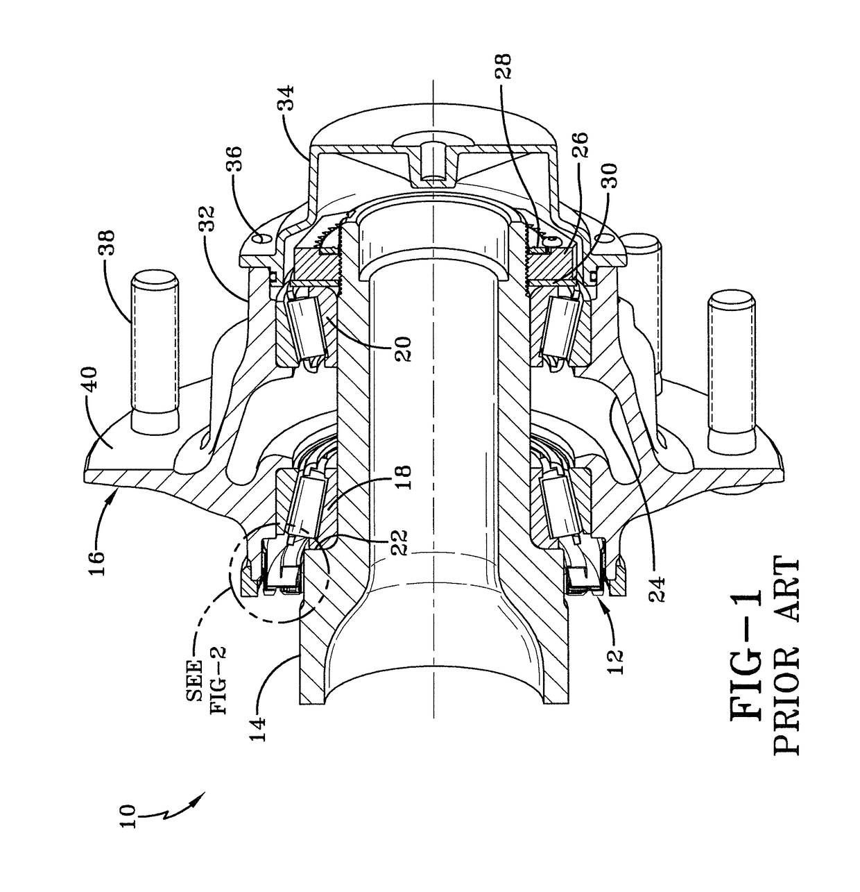
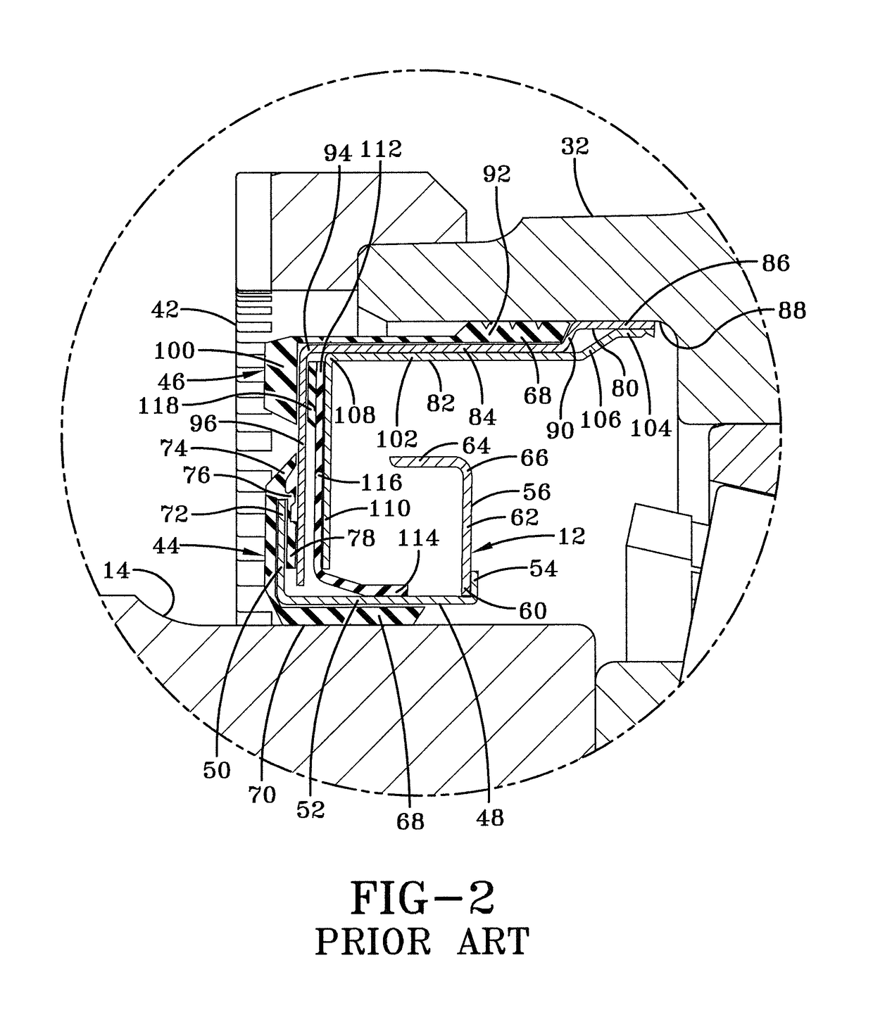
[0020]Turning to FIG. 1, in order to better understand the main seal of the present invention and the environment in which it operates, an axle spindle and wheel end assembly, indicated generally at 10, is shown with a prior art main seal or hub seal 12. An axle depends from and extends transversely across the trailer of a heavy-duty tractor-trailer (not shown). More specifically, and as is known in the art, the axle includes a central tube having a pair of ends (not shown) and a pair of axle spindles 14, with each one of the axle spindles being integrally connected by any suitable means, such as welding, to a respective one of the ends of the central tube, so that the axle is comprised of the central tube and a pair of axle spindles. A typical heavy-duty tractor-trailer includes one or more non-drive axles suspended from the trailer, with each of the axles having a wheel end assembly 16 mounted on each end of the axle. For the sake of clarity, only one axle end and wheel end assemb...


PUM


Abstract

A wheel end assembly for a heavy-duty vehicle includes an axle spindle and a hub rotatably mounted on the axle spindle. A main seal extends radially between the axle spindle and the hub. The seal includes a dynamic portion that seats in a bore formed in the wheel hub, and a static portion that seats on the axle spindle. The static portion includes a rigid carrier that in turn includes a first member, and a second member that is rigidly attached to the first member. An elastomer is bonded to the carrier member and forms a first external lip. The first external lip extends generally parallel to a chamfer formed in an inboard end of the hub. The first external lip, other external features, and internal features prevent contaminants from entering the wheel end assembly, retain lubricant in the assembly, and provide a dynamic expulsion surface to expel contaminants.

Description

CROSS-REFERENCE TO RELATED APPLICATIONS[0001]This application claims the benefit of U.S. Provisional Patent Application Ser. No. 61 / 769,974, which was filed on Feb. 27, 2013.BACKGROUND OF THE INVENTION[0002]Technical Field[0003]The invention relates to wheel end assemblies, and in particular to wheel end assemblies for heavy-duty vehicles, such as tractor-trailers. More particularly, the invention is directed to a main seal or hub seal for a heavy-duty vehicle wheel end assembly that extends radially between a hub of the wheel end assembly and an axle spindle, which prevents contaminants from entering the wheel end assembly and retains lubricant in the wheel end assembly. Still more particularly, the invention relates to a main seal for a heavy-duty vehicle wheel end assembly that includes external features and internal features that optimize the prevention of contaminants from entering the wheel end assembly and retain lubricant in the wheel end assembly, and provide a dynamic expu...

Claims


Application Information

Patent Timeline
Patent Type & Authority Patents(United States)
IPC IPC(8): B60B27/00F16J15/3256F16C33/80F16C33/78
CPCB60B27/0073F16C33/7816F16C33/80F16J15/3256F16C33/7886F16C2326/02F16J15/3236F16J15/447F16C19/364F16C19/548
Inventor WHITE, JAY D.MORRIS, JEFFREY S.GRECA, GERALD A.
Owner TENNECO INC
Learn More