
Method for connecting multiple battery cells of a battery and battery system having a battery with multiple battery cells and multiple battery-cell-monitoring modules which are respectively assigned to a battery cell

Active Publication Date: 2018-03-13
ROBERT BOSCH GMBH
View PDF8 Cites 0 Cited by
  • Summary
  • Abstract
  • Description
  • Claims
  • Application Information

AI Technical Summary

Benefits of technology

This patent relates to a method for controlling the output voltage of a battery. The invention uses a variable update frequency for the control variables, which are determined based on the difference between the desired output voltage and the current output voltage of the battery. This approach minimizes the control error by reducing the frequency of switching states of the battery cells. The update frequency is adjusted based on the control error and the maximum transmission rate of the transmission channel. This method evenly loads the battery cells and minimizes the switching losses caused by random processes. Overall, this invention allows for a more efficient and accurate control of the battery output voltage.

Problems solved by technology

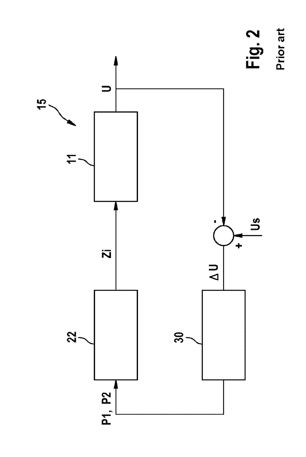
A disadvantage of using a high update frequency for the value of the first controlled variable P1 and for the value of the second controlled variable P2 is that the switching state of each switched-off battery cell 21 of the battery 11 or of each switched-on battery cell 21 of the battery 11 can possibly change on receipt of each new value of the first controlled variable P1 or of the second controlled variable P2 by the respective battery cell monitoring module 22 associated therewith.

Method used


Image

  • Method for connecting multiple battery cells of a battery and battery system having a battery with multiple battery cells and multiple battery-cell-monitoring modules which are respectively assigned to a battery cell
  • Method for connecting multiple battery cells of a battery and battery system having a battery with multiple battery cells and multiple battery-cell-monitoring modules which are respectively assigned to a battery cell
  • Method for connecting multiple battery cells of a battery and battery system having a battery with multiple battery cells and multiple battery-cell-monitoring modules which are respectively assigned to a battery cell

Examples


Embodiment Construction

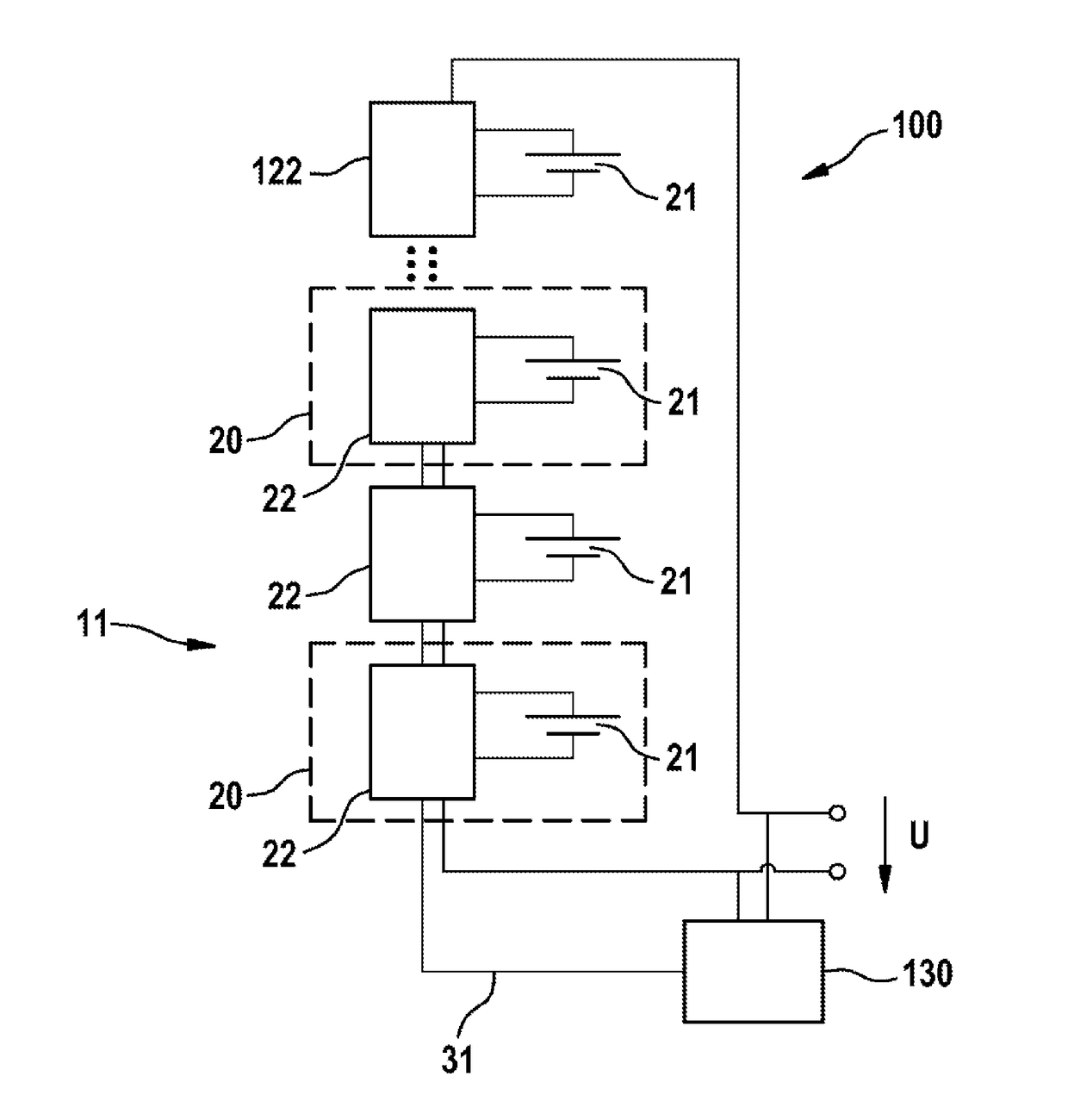
[0029]FIG. 4 shows a battery system 100 according to the invention based on a first embodiment of the invention. Like the battery system depicted in FIG. 1 and known from the prior art, the battery system 100 according to the invention comprises a battery 11 having multiple battery cell units 20 that each comprise a battery cell 21 and a battery cell monitoring module 22 associated with the battery cell 21. In this case too, the multiple battery cells 21 are connectable in series with one another by means of the associated battery cell monitoring modules 22. Further, a central control unit 130 of the battery system 100 according to the invention is also designed to provide controlled variables P1, P2 of each battery cell monitoring module 22 of the battery 11 via a transmission channel in the form of the communication link 31 and to alter the value of the first controlled variable P1 and the value of the second controlled variable P2 such that a magnitude of a control error that is ...


PUM


Abstract

The present invention relates to a method for connecting multiple battery cells (21) of a battery (11), wherein the multiple battery cells (21) can be connected in series to one another, and a single first control variable P1 and a single second control variable P2 are predefined for all the battery cells (21). In this context, in order to generate a desired output voltage of the battery (11), each battery cell (21) is electrically coupled to the battery (11) with a corresponding first probability, defined as a function of the first control variable P1, and in each case electrically decoupled from the battery (11) with a corresponding second probability, defined as a function of the second control variable P2. In addition, a value of the first control variable P1 and a value of the second control variable P2 are respectively predefined repeatedly with an update frequency which is dependent on the desired output voltage of the battery (11) which is to be generated.

Description

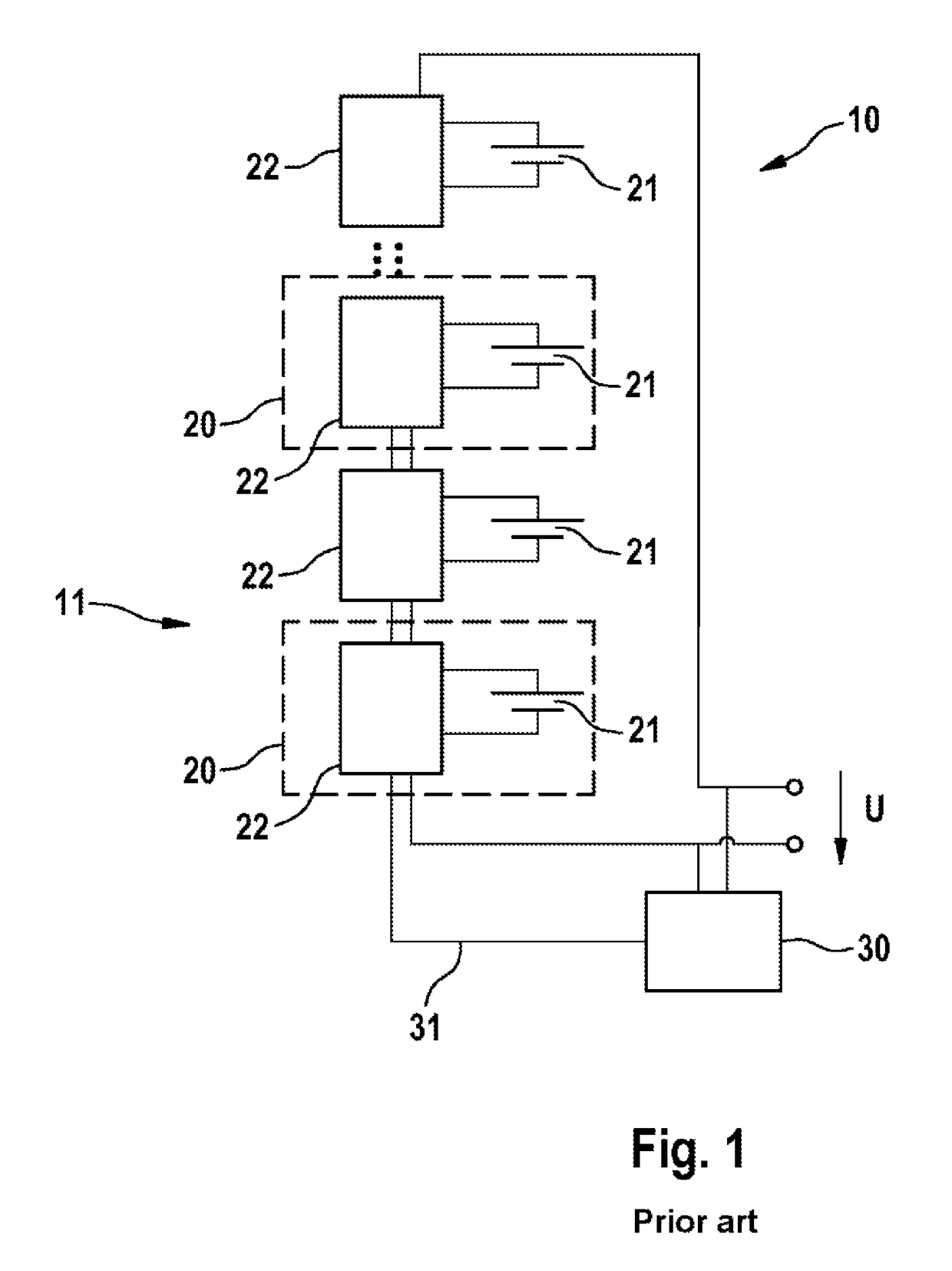
BACKGROUND OF THE INVENTION[0001]The present invention relates to a method for connecting multiple battery cells of a battery. The invention also relates to a battery system having a battery having multiple battery cells, each battery cell having a respective associated battery cell monitoring module arranged in the battery.[0002]FIG. 1 depicts a battery system 10 that is known from the prior art and that comprises a battery 11 having multiple battery cell units (Smart Cell Unit SCU) 20 that each have a battery cell 21 and a battery cell monitoring module (battery cell electronics module or battery cell electronics) 22 associated with the battery cell 21. To simplify the depiction from FIG. 1, only two battery cell units are outlined and each provided with the reference symbol 20. The battery cell monitoring modules 22 allow individual control of the single battery cells 21. To produce an output voltage (total output voltage) U from the battery 11, which is also used as the output v...

Claims


Application Information

Patent Timeline
Patent Type & Authority Patents(United States)
IPC IPC(8): H02J7/00
CPCH02J7/0019H02J7/0021H02J7/0016B60L58/19H02J7/14B60L2240/547Y02T10/70
Inventor PARGA-CACHEIRO, JOSE-LUISHILLENBRAND, PHILIPP
Owner ROBERT BOSCH GMBH
Learn More