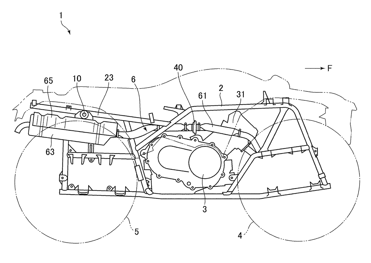
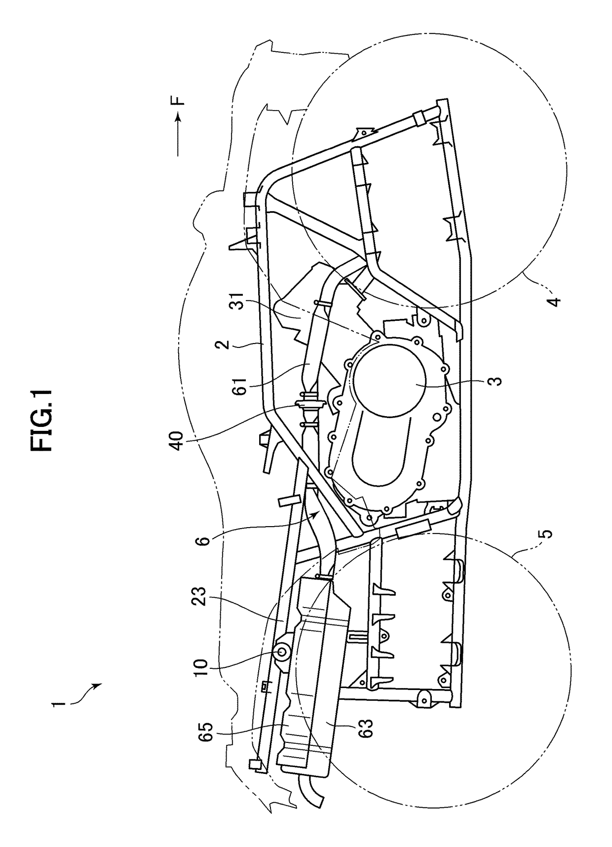
Mount device and vehicle

a technology of mounting device and mounting plate, which is applied in the direction of shock absorber mounting, jet propulsion mounting, transportation and packaging, etc., can solve the problems that the displacement allowance of the exhaust device along with the vibration of the engine cannot be sufficiently enhanced in some cases, so as to improve the displacement allowance and improve the positioning performance

Active Publication Date: 2018-03-20
YAMAHA MOTOR CO LTD
View PDF3 Cites 0 Cited by
  • Summary
  • Abstract
  • Description
  • Claims
  • Application Information

AI Technical Summary

Benefits of technology

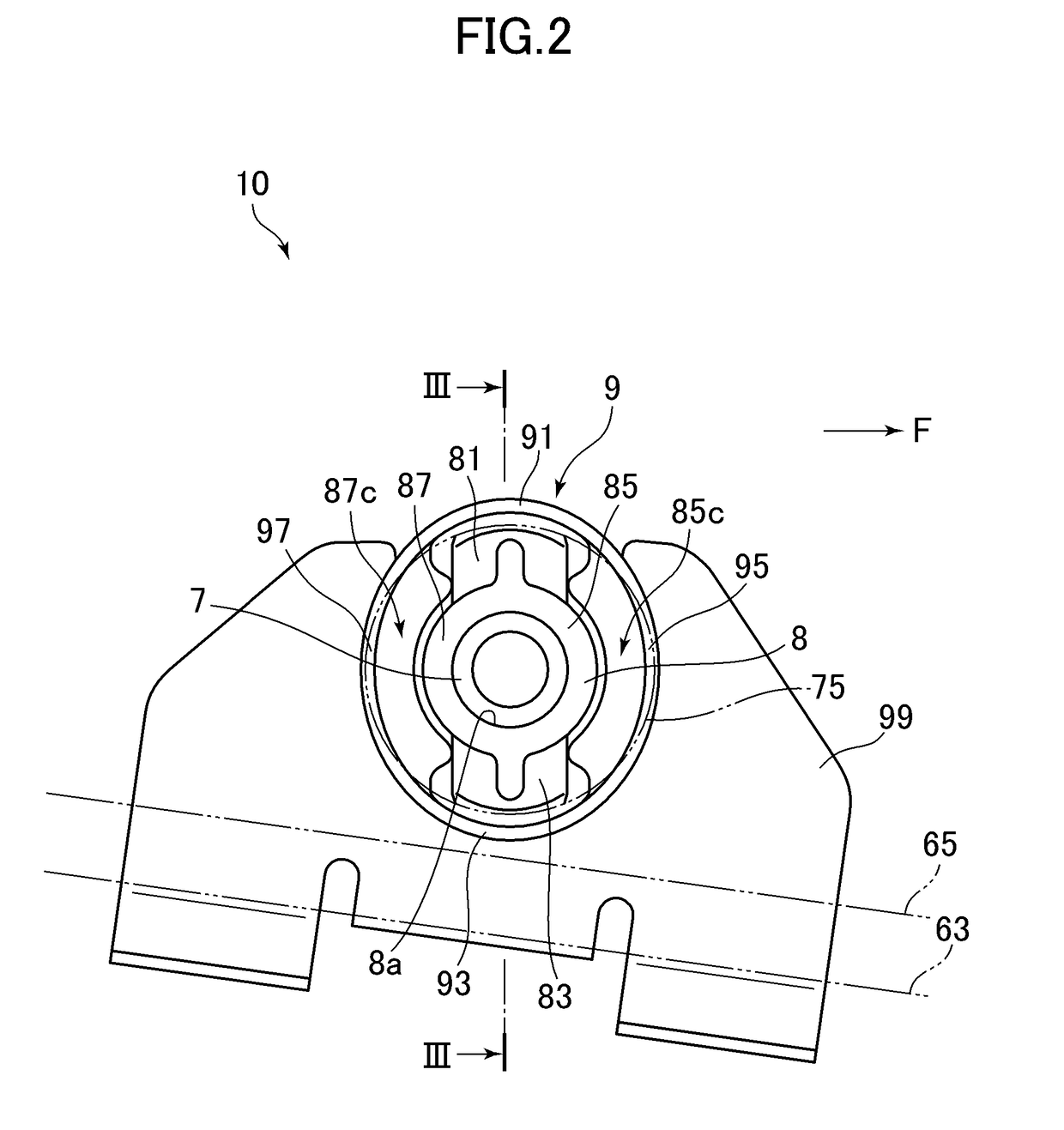
[0007]According to one embodiment of the mount device described above, for example, the positioning performance can be improved by setting the stretchability relatively low in a direction in which projecting portions extend relative to an inner rod, while the displacement allowance can be improved by setting the stretchability relatively high in a direction in which small-thickness portions are arranged relative to the inner rod. Further, projecting portions of a damper are brought into contact with contact surfaces of an outer cover having a larger curvature than that of a circumscribed circle of the damper. Thus, rotation of the damper is suppressed, thereby being capable of suppressing a change in a direction of improving the positioning performance and a direction of improving the displacement allowance.
[0009]According to one embodiment of the vehicle described above, the positioning performance can be improved by setting the stretchability relatively low in the upward and downward direction, while the displacement allowance can be improved by setting the stretchability relatively high in the rightward and leftward direction (e.g., direction in which the small-thickness portions are positioned with respect to the inner rod).

Problems solved by technology

Therefore, with the tubular rubber damper as described in the '643 reference, the allowance for the displacement of the exhaust device along with the vibration of the engine cannot be sufficiently enhanced in some cases.

Method used


Image

  • Mount device and vehicle
  • Mount device and vehicle
  • Mount device and vehicle

Examples


Embodiment Construction

[0026]The terminology used herein is for the purpose of describing particular embodiments only and is not intended to be limiting of the invention. As used herein, the term “and / or” includes any and all combinations of one or more of the associated listed items. As used herein, the singular forms “a,”“an,” and “the” are intended to include the plural forms as well as the singular forms, unless the context clearly indicates otherwise. It will be further understood that the terms “comprises” and / or “comprising,” when used in this specification, specify the presence of stated features, steps, operations, elements, and / or components, but do not preclude the presence or addition of one or more other features, steps, operations, elements, components, and / or groups thereof.

[0027]Unless otherwise defined, all terms (including technical and scientific terms) used herein have the same meaning as commonly understood by one having ordinary skill in the art to which this invention belongs. It wi...


PUM

PropertyMeasurementUnit
elasticaaaaaaaaaa
thicknessaaaaaaaaaa
curvatureaaaaaaaaaa

Abstract

A mount device includes an inner rod, a damper made of an elastic material to be mounted to the inner rod, and an outer cover to be mounted to the damper. The damper includes a plurality of projecting portions projecting radially outward from the inner rod and small-thickness portions thinner than the plurality of projecting portions in a radial direction. Spaces are formed radially outward of the small-thickness portions. The outer cover includes a plurality of contact surfaces to respectively come into contact with the plurality of projecting portions. The contact surfaces have a larger curvature than that of a circumscribed circle of the damper.

Description

CROSS-REFERENCE TO RELATED APPLICATION[0001]The present application claims priority from Japanese application JP2016-85411 filed on Apr. 21, 2016, the content of which is hereby incorporated by reference into this application.BACKGROUND OF THE INVENTIONDescription of the Related Art[0002]In a vehicle such as an all-terrain vehicle (ATV), an exhaust device connected to an engine is suspended from a vehicle body frame. In a case where the engine is mounted to the vehicle body frame through the intermediation of a rubber damper so as to absorb vibration of the engine, the exhaust device is displaced relative to the vehicle body frame along with the vibration of the engine. Therefore, in order to allow the displacement described above, the exhaust device is suspended from the vehicle body frame through the intermediation of the rubber damper in some cases.SUMMARY OF THE INVENTION[0003]Incidentally, a vertical position of the exhaust device suspended from the vehicle body frame is determ...

Claims


Application Information

Patent Timeline
Patent Type & Authority Patents(United States)
IPC IPC(8): B60K13/04F16F15/08B60K5/12
CPCB60K13/04B60K5/1208F16F15/08F16F2230/0005F16F2224/025F16F1/3821F16F1/3863
Inventor OGURI, KIYOHIKONISHIHARA, KAZUHIROSOMA, MITSUHARU
Owner YAMAHA MOTOR CO LTD
Why Eureka
Try Eureka