
Modular isolating system

a technology of isolating system and module, which is applied in the direction of vibration dampers, machine supports, loudspeaker casing supports, etc., can solve the problems of affecting the quality of sound from the audio equipment, the housing may end up falling off the support surface and being damaged, and the vibration of the audio equipment may generate substantial vibrations, etc., to reduce the vibration transfer, reduce the tendency of the equipment, and reduce the level of a pi

Active Publication Date: 2018-03-20
D MORRISON CONSULTING
View PDF6 Cites 6 Cited by
  • Summary
  • Abstract
  • Description
  • Claims
  • Application Information

AI Technical Summary

Benefits of technology

[0003]There is therefore a need in the art for a device or system that will aid in reducing the level of vibration of a piece of audio equipment or that will reduce the tendency of the equipment to travel across a support surface when operating, or that will reduce the transfer of vibration from the audio equipment to the support surface upon which the equipment rests; or that will reduce the transfer of vibration to the audio equipment from the support surface.
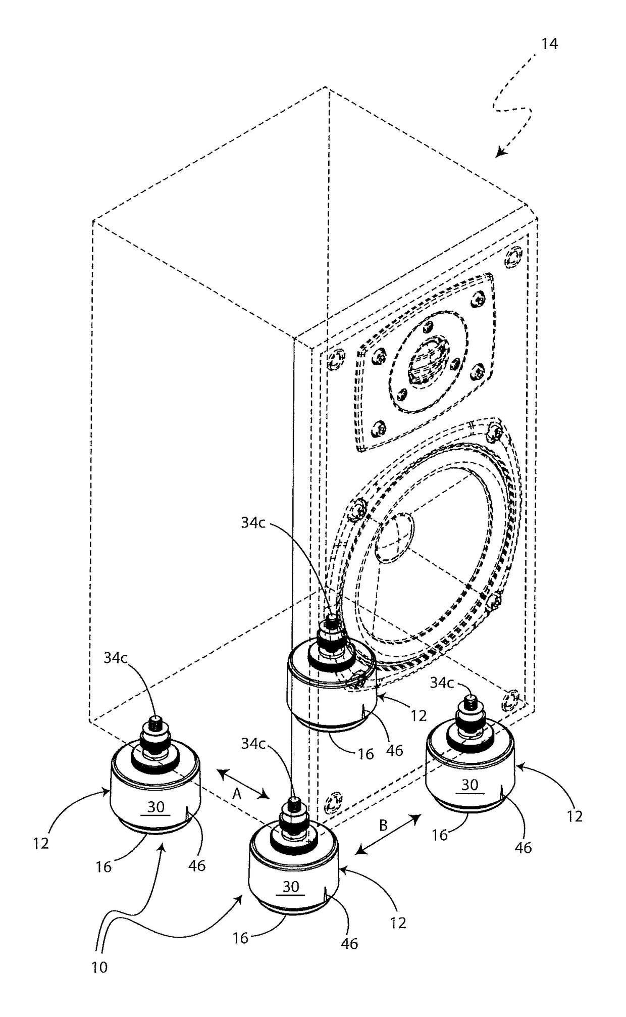
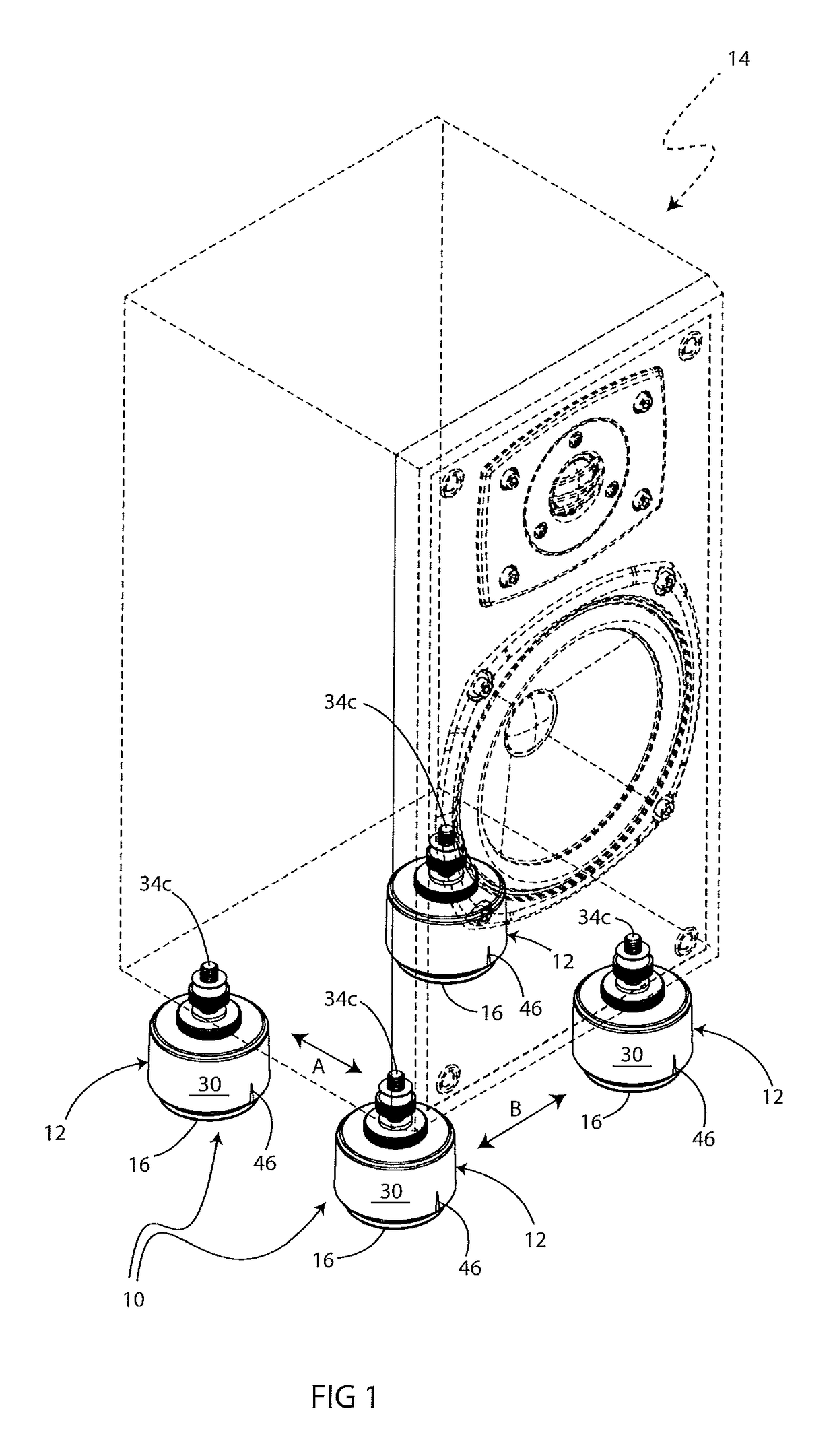
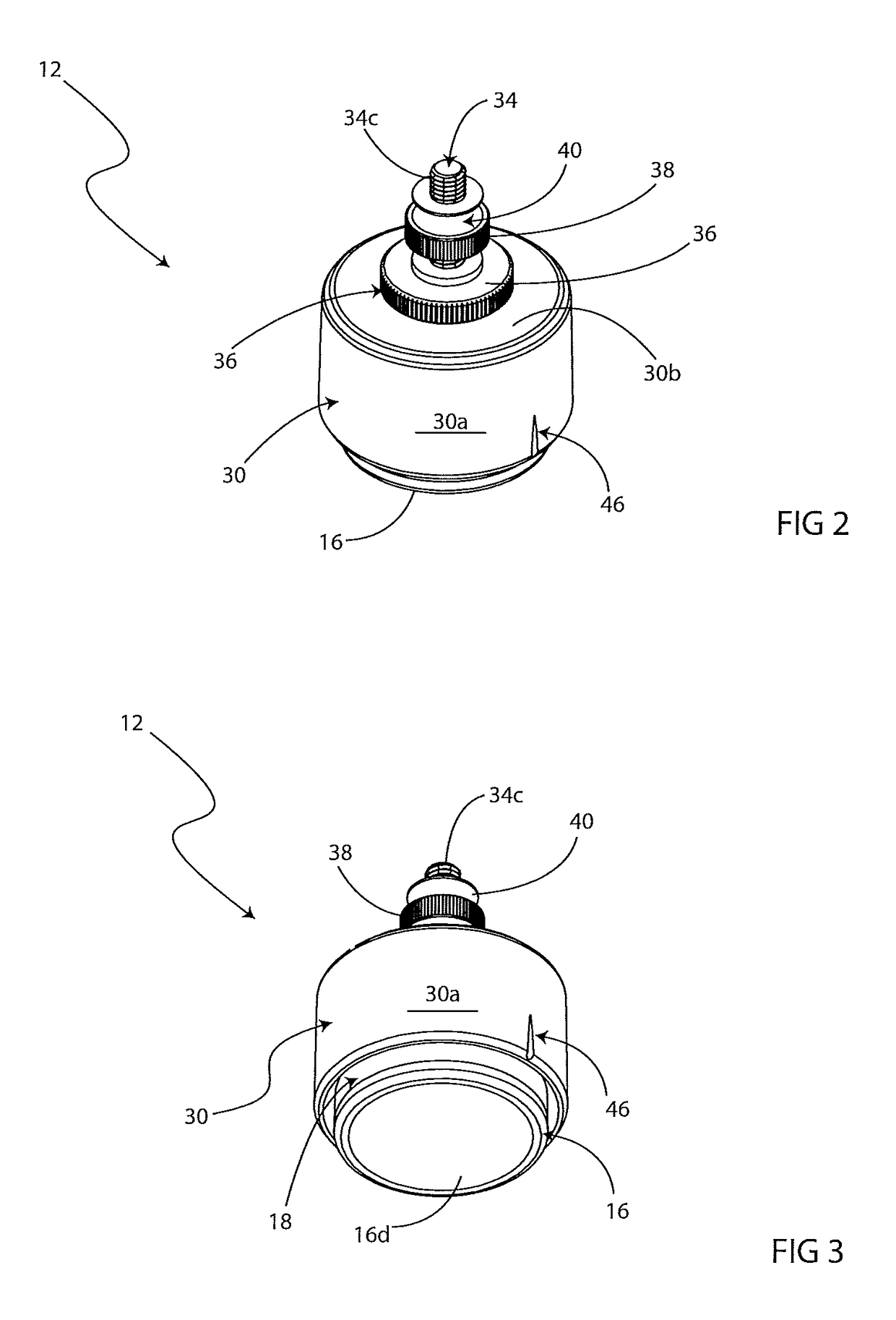
[0008]The isolating assemblies disclosed herein may not have a bottom frame. Instead, the isolating assemblies may be attached or hung from a bottom wall of the piece of equipment with which they are engaged. The lower part of the isolating assembly may sit on a support surface, such as a floor, and the lower isolating assembly's hole may be of an oval shape. The connector that connects the upper and lower isolating assemblies may be oval in cross-sectional shape. The oval shape tends to help create and maintain polarity. A visual direction indicator may be provided in any suitable location on the isolating assembly and indicates a particular direction. The visual direction indicators of several individual isolating assemblies may be aligned and this results in the polarizing components in the isolating assemblies tending to be aligned with each other. The isolating assemblies will all then tend to polarize motion transferred to them in much the same manner. The visual direction indicator makes it easy for an end-user to correctly orient all of the isolating assemblies used in the modular isolating system with each other.
[0009]The disclosed isolating assemblies may be frameless. The soft rubber of the isolating assembly may expand as the device is used for a period of time and therefore may loosen its grip on the captured polarized connector. The isolating assembly may therefore be provided with a rigid ring, preferably a metal ring that may be snapped into a groove on an exterior surface of the rubber components of the device. This metal ring may help the rubber to keep its shape and retain its engagement with the flanged connector.
[0010]In other embodiments, a bolt may be utilized to attach the isolating assembly to a bottom wall of the piece of equipment with which the isolating assembly is engaged. There may also be a movable lock nut that aids in compensating for uneven surfaces or aids in tilting the piece of equipment at an angle.

Problems solved by technology

Audio equipment may generate substantial vibrations during operation or may be sensitive to vibrations in the supporting structure.
These vibrations may transfer from the sound generating components to the housing of the equipment or may be affected by vibrations in the structure and support that affect performance and clarity.
If the movement of the housing across the support surface is not halted, the housing may ultimately fall off the support surface and be damaged.
Instead, the vibration may be transferred to the support surface itself and can lead to the generation of unwanted sounds that may distort the quality of the sound from the audio equipment.
Turntables, for example, a turntable are sensitive to external vibrations that may result in the unwanted vibrations being reproduced through the system or may result in a needle on the turntable skipping.
The soft rubber of the isolating assembly may expand as the device is used for a period of time and therefore may loosen its grip on the captured polarized connector.

Method used


Image

  • Modular isolating system
  • Modular isolating system
  • Modular isolating system

Examples


third embodiment

[0049]FIGS. 16-20 show an isolating assembly 212 that may be utilized as part of a modular isolating system. Isolating assembly 212 may be referred to herein as a “polarizing puck” and will be described hereafter in greater detail.

fourth embodiment

[0050]FIGS. 21-25 show an isolating assembly 312 that may be utilized as part of a modular isolating system. Isolating assembly 312 will be described hereafter in greater detail.

fifth embodiment

[0051]FIGS. 26-30 show an isolating assembly 412 that may be utilized as part of a modular isolating system. Isolating assembly 412 will be described hereafter in greater detail.


PUM


Abstract

An isolating assembly, a modular isolating system including the assembly and a method of using the same. The system includes a plurality of individual isolating assemblies, each isolating assembly being engageable with an article; and wherein each isolating assembly includes a lower isolator that rests upon a flat surface; an upper isolator that is engageable with the article; and a connector having first and second ends. The first end of the connector engages the lower isolator and the second end of the connector engages the upper isolator. The upper isolator is positioned above the lower isolator and is movable relative to the lower isolator when vibration from the article is transferred to the upper isolator. The connector may be a polarizing connector that restricts the movement of the upper isolator in a first direction but permits movement thereof in a second direction that is orthogonal to the first direction.

Description

BACKGROUND OF THE INVENTIONTechnical Field[0001]This invention relates generally to audio equipment. More particularly the invention relates to dampening vibration in audio equipment. Specifically, the invention is directed to an isolating assembly, a modular isolating system incorporating the assembly and a method of using the same; where the assembly includes an upper isolator engageable with the equipment, a lower isolator that engages a support surface; and a connector extending between the upper and lower isolators, where the connector permits the upper isolator to move relative to the lower isolator when vibrations are transferred to the upper isolator from the audio equipment.Background Information[0002]Audio equipment may generate substantial vibrations during operation or may be sensitive to vibrations in the supporting structure. These vibrations may transfer from the sound generating components to the housing of the equipment or may be affected by vibrations in the struct...

Claims


Application Information

Patent Timeline
Patent Type & Authority Patents(United States)
IPC IPC(8): F16M13/00F16F3/087F16F15/08
CPCF16F15/08F16F3/0873F16F2232/08H04R1/026
Inventor MORRISON, DAVID
Owner D MORRISON CONSULTING
Learn More