Control system and method for helicopter electrically-driven tail rotor

A technology of control system and helicopter, which is applied in the direction of aircraft power transmission, aircraft power device, aircraft parts, etc., can solve the problems of difficult assembly and maintenance, high driving difficulty, heavy structure weight, etc., achieve convenient driving, reduce operation difficulty, improve performance effect

Active Publication Date: 2018-09-14
HEFEI UNIV OF TECH
View PDF5 Cites 5 Cited by
  • Summary
  • Abstract
  • Description
  • Claims
  • Application Information

AI Technical Summary

Problems solved by technology

[0003] The existing helicopter tail rotor system has the characteristics of large structural weight, large energy loss, large vibration and noise, possible jamming of the control rod system, difficulty in assembly and maintenance, etc.
The existing variable pitch structure of helicopters mostly uses a worm gear mechanism to control the movement of the variable pitch ring, and the structure is relatively complicated.
Moreover, in the variable-pitch operation, the helicopter balance and steering are controlled entirely by the driver stepping on the pedals. The driving is difficult and unstable, and it is easy to vibrate.

Method used


Image

  • Control system and method for helicopter electrically-driven tail rotor
  • Control system and method for helicopter electrically-driven tail rotor
  • Control system and method for helicopter electrically-driven tail rotor

Examples


Embodiment 1

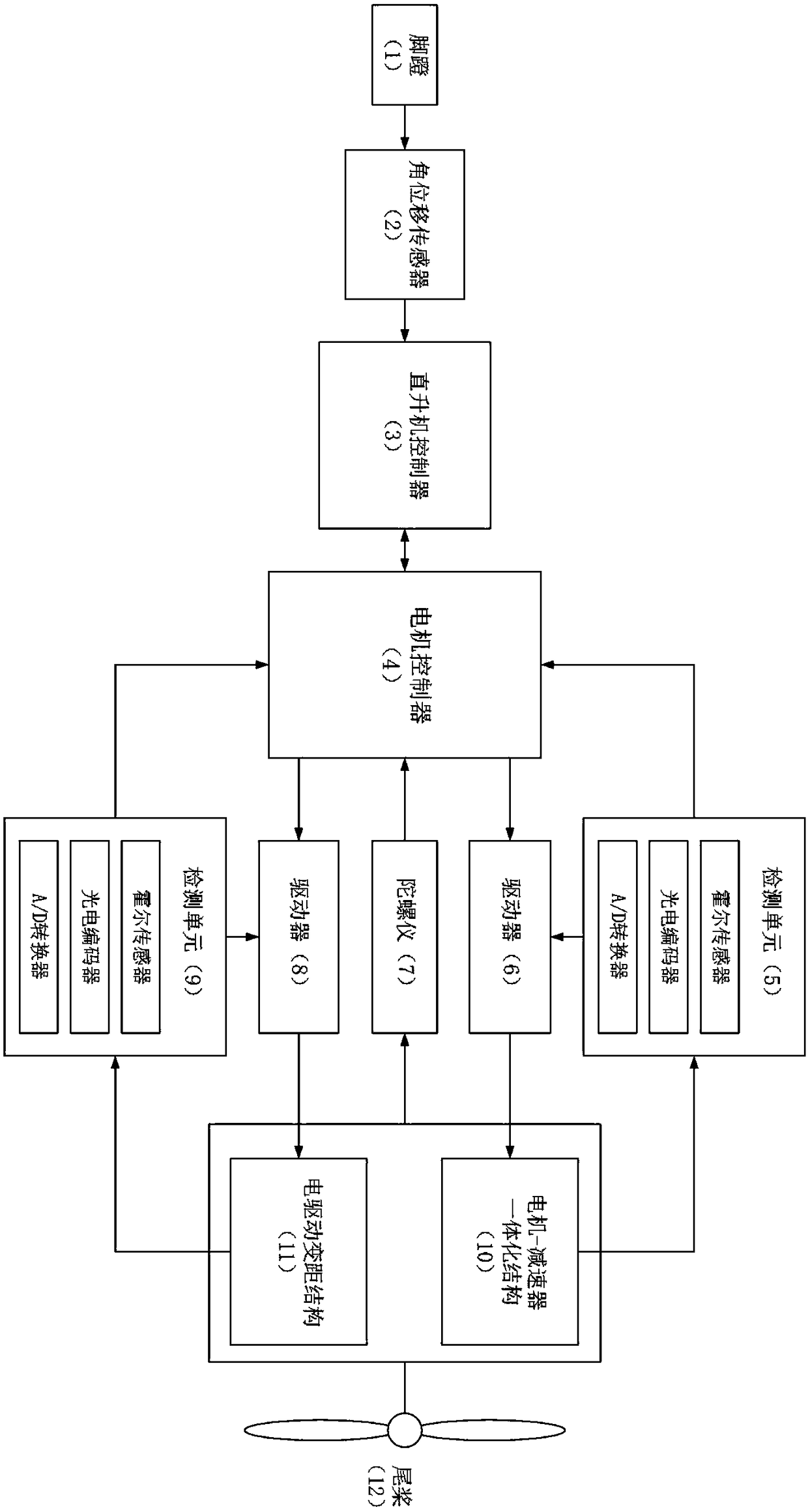
[0037] like figure 1 As shown, a helicopter electric drive tail rotor control system includes: an angular displacement sensor 2, a helicopter controller 3, a motor controller 4, a first detection unit 5, a first driver 6, a gyroscope 7, a second driver 8, A second detection unit 9 , a motor-reducer integrated structure 10 , and an electric drive variable pitch structure 11 . in:

[0038] The angular displacement sensor 2 is connected with the pedal 1 of the helicopter and the helicopter controller 3 respectively, and is used to detect the angle change of the pedal 1 to obtain an angle signal, and transmit the angle signal to the helicopter controller 3 .

[0039] The gyroscope 7 is installed at the tail of the helicopter, and is connected with the motor controller 4 and the helicopter controller 3 respectively, and is used to detect the attitude change of the helicopter to obtain an attitude signal, and transmit the attitude signal to the motor control device 4 and the heli...

Embodiment 2

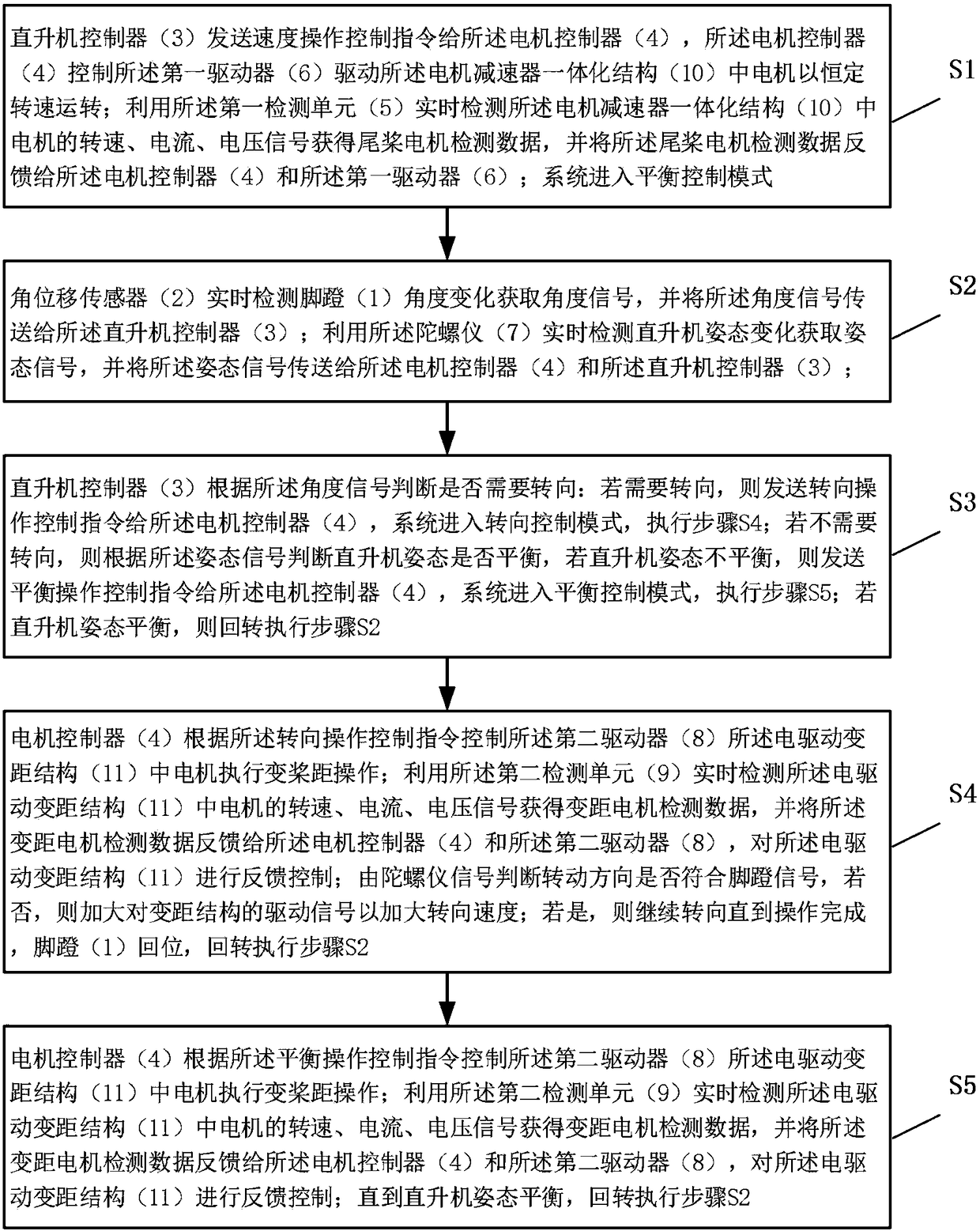
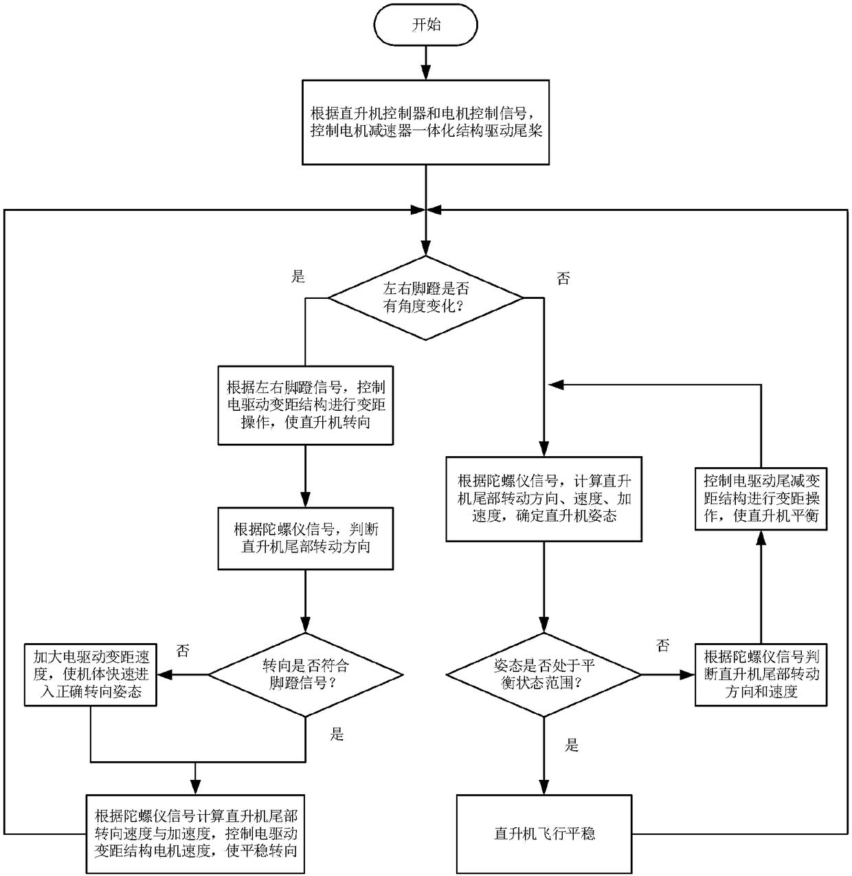
[0053] like figure 2 and image 3 As shown, based on the control system provided in Embodiment 1, this embodiment provides a method for controlling the electrically driven tail rotor of a helicopter, including the following steps:

[0054] Step S1, using the helicopter controller 3 to send a speed operation control command to the motor controller 4, and the motor controller 4 controls the first driver 6 to drive the motor in the motor-reducer integrated structure 10 to Constant speed operation. Use the first detection unit 5 to detect in real time the rotational speed, current and voltage signals of the motor in the motor-reducer integrated structure 10 to obtain the detection data of the tail rotor motor, and feed back the detection data of the tail rotor motor to the motor The controller 4 and the first driver 6 form a feedback control.

[0055] The beneficial technical effect of the above-mentioned feedback control is: when the external load changes, such as when the he...


PUM


Abstract

The invention relates to a control system and method for a helicopter electrically-driven tail rotor. The control system comprises a pedal, an angular displacement sensor, a helicopter controller, a motor controller, a driver for a tail rotor driving motor, a motor driver of a tail rotor variable pitch structure, a detection unit, a gyroscope, a motor-reducer integrated structure capable of driving the tail rotor to rotate, and an electrically-driven variable pitch structure. By use of the control method, according to a pedal angle change and a helicopter tail gesture change of gyroscope detection, the revolving speed of the tail rotor driving motor is automatically controlled, and a variable pitch structure is regulated so as to realize the balance or the diversion of the helicopter. Theinvention provides the control system and method for the helicopter electrically-driven tail rotor, and replaces the internal combustion engine driving and the excessive transmission shaft of a traditional helicopter, so that the quick and stable automatic balance and diversion of the helicopter can be realized, operation difficulty is reduced, and reliability and stability are enhanced so as to be favorable for accelerating the technology of an electric helicopter to be progressed and developed.

Description

technical field [0001] The invention relates to the field of helicopter design and control, in particular to a helicopter electric drive tail rotor control system and method. Background technique [0002] The power source of the traditional helicopter tail rotor is generally from the main engine, which is transmitted to the tail rotor through the reducer and the transmission shaft. At present, the helicopter tail rotor is generally composed of intermediate reducer, tail drive shaft, tail reducer, tail rotor pitch change rod and other components, wherein the intermediate reducer, tail drive shaft, and tail reducer transfer the energy from the main reducer to Tail rotor, which drives the tail rotor to rotate; the pilot controls the pedal to drive the tail rotor pitch change rod through the control line, thereby changing the angle of attack of the tail rotor blade and changing the thrust (pull force) of the tail rotor blade to achieve the purpose of helicopter balance or direct...

Claims


Application Information

Patent Timeline
Patent Type & Authority Applications(China)
IPC IPC(8): B64D35/02B64D35/00
CPCB64D35/00B64D35/02
Inventor 甄圣超李传阳黄康赵韩孙浩陈盼盼张雁欣吴兵兵刘荣耀曲东旭
Owner HEFEI UNIV OF TECH
Why Eureka
Try Eureka