Lawnmower with vibration reduction

a lawnmower and vibration reduction technology, applied in the field of wheel-mounted lawnmowers, can solve the problems of tingling and numbness, damage to the lawnmower components, and user discomfort, and achieve the effects of reducing vibration, facilitating cutting function, and reducing vibration

Inactive Publication Date: 2006-07-20
INGEMANSSON TECH
View PDF8 Cites 5 Cited by
  • Summary
  • Abstract
  • Description
  • Claims
  • Application Information

AI Technical Summary

Benefits of technology

[0016] Preferably said insulator is adapted to reduce any vibrations in said first unit to be transmitted to said second unit which is connected to said operating means.
[0017] Said first unit comprises preferably a frame for attaching said cutting device and said motor. Further said first unit suitably has a protective cover which at least partially surrounds said cutting device. The protective cover performs a protecting function and is also suitably adapted to produce convenient currents of air when the lawnmower is in operation, thus facili...

Problems solved by technology

The motor-driven devices of the type mentioned above, however, result in vibrations from, for instance, motor and rotating tools being transmitted to the handle and then on to the user.
This vibration problem may cause problems for the user, especially in daily and frequent use, in the form of vibration injuries in arms and hands.
A common vibration injury is the white finger syndrome which means that the blood flow to the fingers is reduced, resulting in tingling and numbness.
Due to the vibrations, also components of the lawnmower may be damaged and/or come loose.
However, a remaining problem is that the motor in this case is subjected to high vibration levels, which in turn may result ...

Method used


Image

  • Lawnmower with vibration reduction
  • Lawnmower with vibration reduction
  • Lawnmower with vibration reduction

Examples


first embodiment

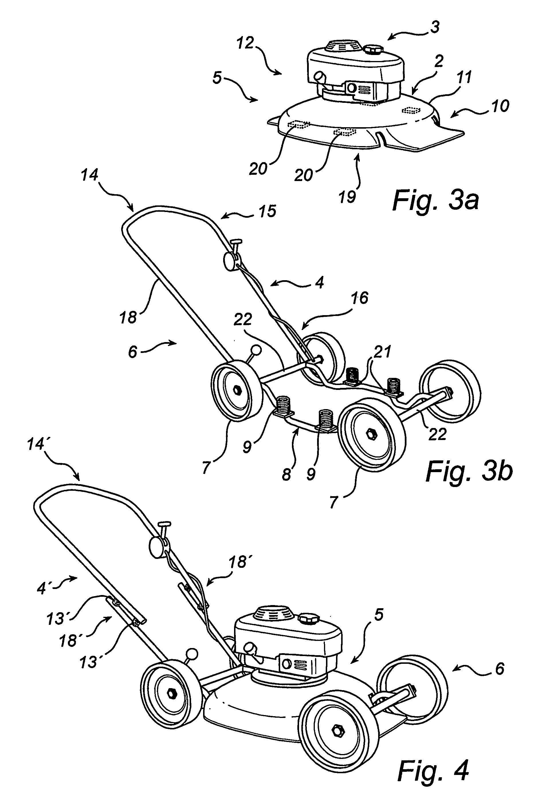
[0036]FIG. 3a shows a first unit 5 of the lawnmower 1 according to the The first unit comprises in this case suitably the hood-shaped frame 10 for stable attachment of the motor 3 and the cutting device 2. The hood-shaped frame 10 with its protective cover 10 surrounds, peripherally and above, a rotatable blade 19 of the cutting device 2. The protective cover 11 has an opening for the blade (directed towards the base of the lawnmower) to perform the cutting function of the lawnmower. The hood-shaped frame 10 is preferably cast in one piece which is made of metal such as steel or aluminium or alternatively pressed metal sheet or a rigid plastic material. As is evident from FIG. 3a, the rectangular frame 10 has in each corner portion a first fixing portion 20 for an insulator 9. The upper portions of the first unit can be seen as a body 12, which may of course comprise a plurality of adjusted protective hoods for, for instance, the motor 3.

[0037]FIG. 3b shows a second unit 6 of the l...

third embodiment

[0048]FIG. 5a shows a lawnmower according to the invention. The lawnmower is provided with insulators 9″ which are fixed to the protective cover 11 in a clamp 17″ and in the wheel frame 8 at each wheel 7. The insulators 9″ are preferably arranged so as to be longitudinally compressed owing to the weight of the first unit 5, but may of course be arranged so as to be subjected to tractive forces instead. It goes without saying that the insulators 9″ can be arranged in some other way so as to be subjected to a combination of tractive and compressive forces and / or shear forces.

[0049] The insulators 9″ according to the third embodiment are made, for instance, of foamed polyurethane or other suitable materials that exhibit properties according to the intentions of the invention.

[0050] Any stress that exceeds normal use is suitably relieved by limit stops (not shown) to prevent the insulators from being subjected to excessive stress levels which may cause a reduction of the life of the in...

fourth embodiment

[0056]FIG. 7b also shows a portion of the protective cover 11, which portion may consist of another suitable part of the first unit 5. The protective cover 11 has a recess 35′″ which is adapted to be diametrically slightly larger than the fixing means 32′″, for instance as illustrated in FIG. 7b. An insulator 9′″ is mounted on the underside of the protective cover 11. The insulator 9′″ is preferably sleeve-shaped with an inner cylindrical cavity and a through hole 36′″ which is adjusted to the fixing means 32′″. FIG. 8a shows an insulator 9′″ with a cylindrical peripheral shape. FIG. 8b shows another example of an insulator 9″″ which has a square peripheral shape. Of course, the insulator 9′″; 9″″ can be designed in many different ways and still perform a similar damping function according to the intentions of the invention. in FIG. 7b, a washer 34′″ and a nut 33′″ are arranged on the threaded fixing means 32′″ at the through hole 36′″ of the insulator.

[0057] With reference once mo...


PUM


Abstract

The invention relates to a wheel-mounted lawnmower (1) or the like of the type comprising a cutting device (2) which is connected to a motor (3) for performing a cutting function, the lawnmower (1) being operated by an operating means (4). The lawnmower (1) has a first unit (5) which is provided with said cutting device (2) and said motor (3), a second unit (6) which has at least two rotatable wheels (7) for moving the lawnmower relative to a base, a wheel frame (8) for arranging the wheels and for arranging said operating means (4) on said wheel frame (8), and an insulator (9) which is arranged to at least partially mutually connect said first (5) and second (6) unit to reduce any vibrations between said units (5, 6). The invention also relates to an insulator arranged on a lawnmower or the like. The invention also concerns us eof a lawnmower or the like as stated above.

Description

FIELD OF THE INVENTION [0001] The present invention relates to a wheel-mounted lawnmower or the like of the type comprising a cutting device which is connected to a motor for performing a cutting function, the lawnmower being operated by an operating means. The invention also relates to an insulator arranged on a lawnmower or the like. The invention also concerns use of a lawnmower or the like. BACKGROUND ART [0002] Lawnmowers and the like relate to motor-driven devices which in the first place perform a cutting operation. Examples of such lawnmowers are manual rotary lawnmowers, cylinder lawnmowers and, in some cases, chopper mowers. Not only lawnmowers but also wheel-mounted and motor-driven vertical cutters and moss cutters are concerned. Other conceivable examples are wheel-mounted aerators, peat cutters, rotary cultivators and trimmers. [0003] The motor-driven devices of the type mentioned above, however, result in vibrations from, for instance, motor and rotating tools being t...

Claims


Application Information

Patent Timeline
IPC IPC(8): A01D34/03A01D34/82
CPCA01D34/82
Inventor LINDELL, HANS
Owner INGEMANSSON TECH
Why Eureka
Try Eureka