Exhaust turbine equipped with exhaust control valve
a technology of exhaust gas control valve and exhaust gas turbine, which is applied in the direction of valve operating means/release devices, machines/engines, mechanical equipment, etc., can solve the problems of not firmly maintaining the valve body at an expected location, reduce the vibration level of the exhaust gas control valve, reduce the number of components and assembly costs, and reduce the effect of effective results
- Summary
- Abstract
- Description
- Claims
- Application Information
AI Technical Summary
Benefits of technology
Problems solved by technology
Method used
Image
Examples
first embodiment
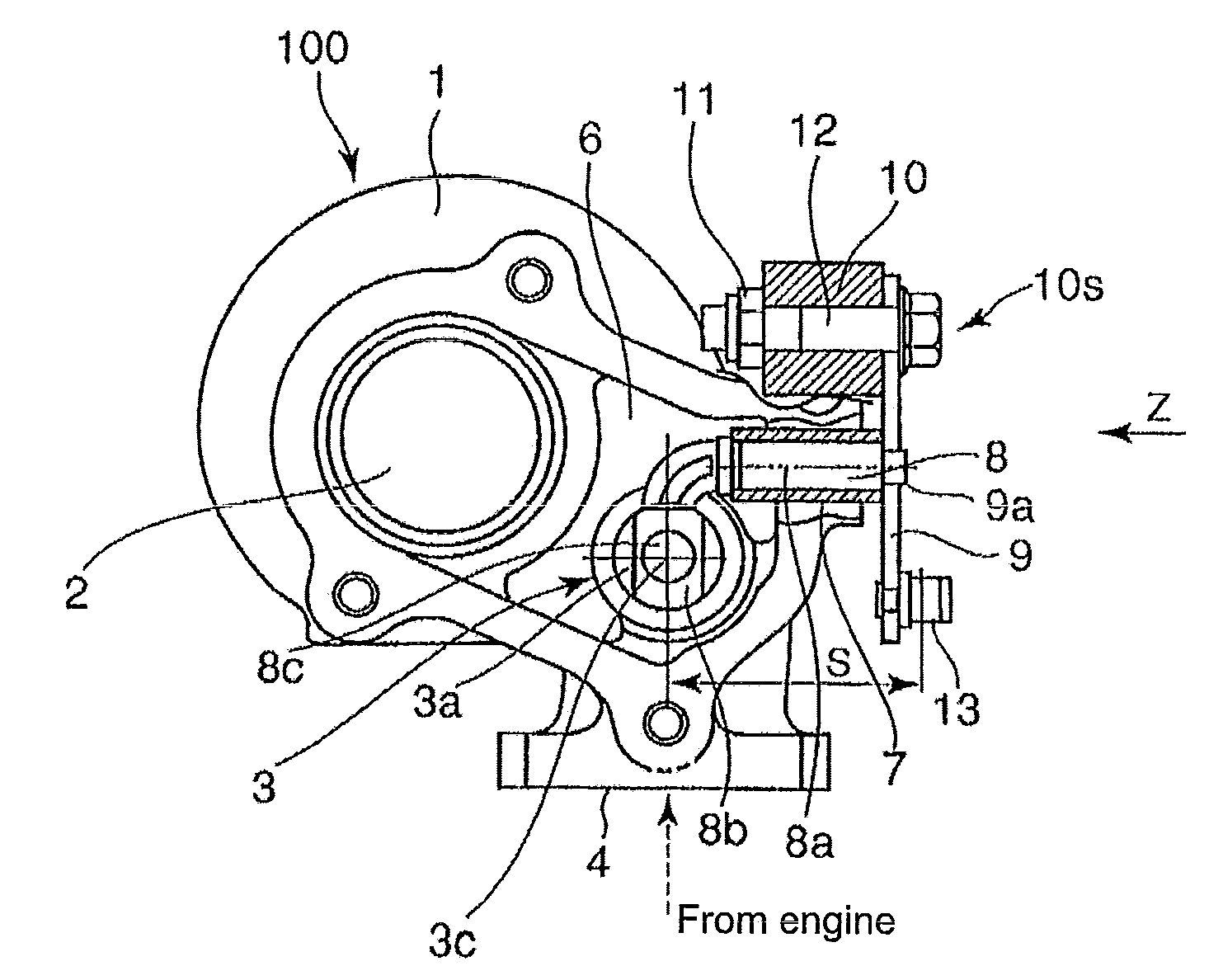
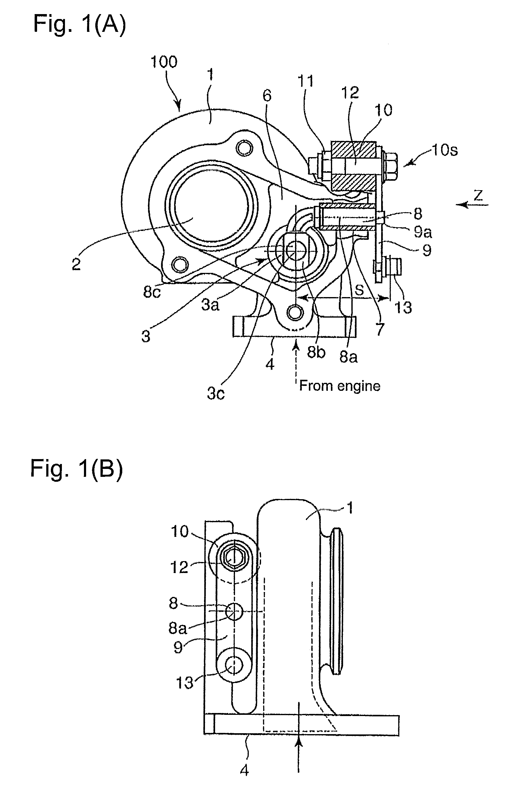
[0043]FIG. 1(A) shows the structure of the waste gate valve (the exhaust gas flow rate control valve) as well as the structure around the waste gate valve in the exhaust gas turbine of the exhaust gas turbocharger, according to the first embodiment of the present invention; FIG. 1(B) shows a view as to the Z-arrow in FIG. 1(A).
[0044]The exhaust gas turbine 100 shown in FIGS. 1(A) and 1(B) comprises a turbine casing 1 in which a turbine 2 (details not shown) is provided with a waste gate valve 3. The waste gate valve 3, as shown in FIG. 3(A) and FIG. 3(B), is for diverging the exhaust gas emitted from the engine (not shown) to the turbine 2 via an exhaust gas passage 6, in the exhaust gas passage 6 located upstream of the turbine 2 so that the diverged exhaust gas bypasses the turbine 2 and flows to an exhaust gas outlet passage 5a via an exhaust gas bypass passage 5. In addition, the numeral 4 denotes an exhaust gas inlet flange.
[0045]As is the case with FIGS. 3(A) and 3(B), a valve...
second embodiment
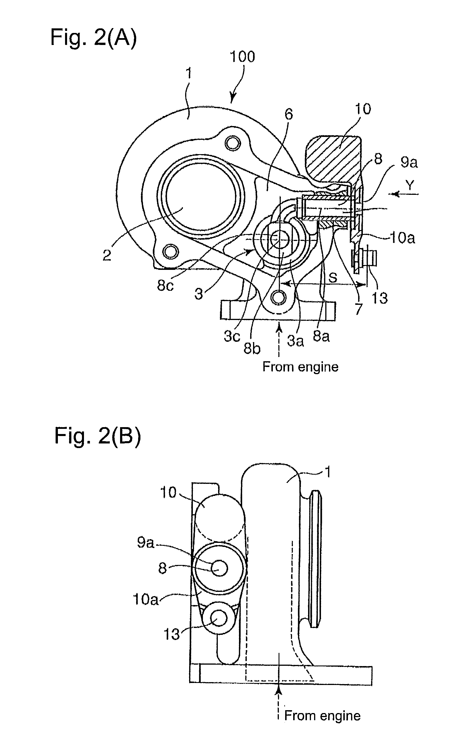
[0057]FIG. 2(A) shows the structure of the waste gate valve (the exhaust gas flow rate control valve) as well as the structure around the waste gate valve in the exhaust gas turbine of the exhaust gas turbocharger, according to the second embodiment of the present invention; FIG. 2(B) shows a view as to the Y-arrow in FIG. 1(A).
[0058]In this second embodiment as shown in FIG. 2(A), the arm 10a and the weight 10 are formed as a single-piece construction made by casting or forging. The middle part of the arm 10a is fitted to the support axis (shaft)) 8 by means of the caulking device 9a. Other configuration or component arrangement is the same as that of the first embodiment; the common symbols or numerals are used for the common components in the first and the second embodiments
[0059]The second embodiment brings effective results, as is the case with the first embodiment. In addition, since the arm 10a and the weight 10 are formed as a single-piece construction made by casting or for...
PUM
 Abstract
Description
Claims
Application Information
 - R&D
- Intellectual Property
- Life Sciences
- Materials
- Tech Scout
- Unparalleled Data Quality
- Higher Quality Content
- 60% Fewer Hallucinations
Browse by: Latest US Patents, China's latest patents, Technical Efficacy Thesaurus, Application Domain, Technology Topic, Popular Technical Reports.
© 2025 PatSnap. All rights reserved.Legal|Privacy policy|Modern Slavery Act Transparency Statement|Sitemap|About US| Contact US: help@patsnap.com


