Actively stabilized payload support apparatus and methods

a payload support and active stabilizer technology, applied in the direction of instruments, stands/trestles, camera body details, etc., can solve the problems of not being able to provide consistent stabilization control, most passive stabilizers require significant training time and effort to become technically proficient in their use,

Active Publication Date: 2018-03-20
WAGNER STEVEN D +2
View PDF5 Cites 11 Cited by
  • Summary
  • Abstract
  • Description
  • Claims
  • Application Information

AI Technical Summary

Problems solved by technology

Most passive stabilizers require significant training time and effort to become technically proficient in their use.
Although a variety of camera stabilization systems are available, challenges still remain in providing consistent stabilization control of payload platforms.

Method used


Image

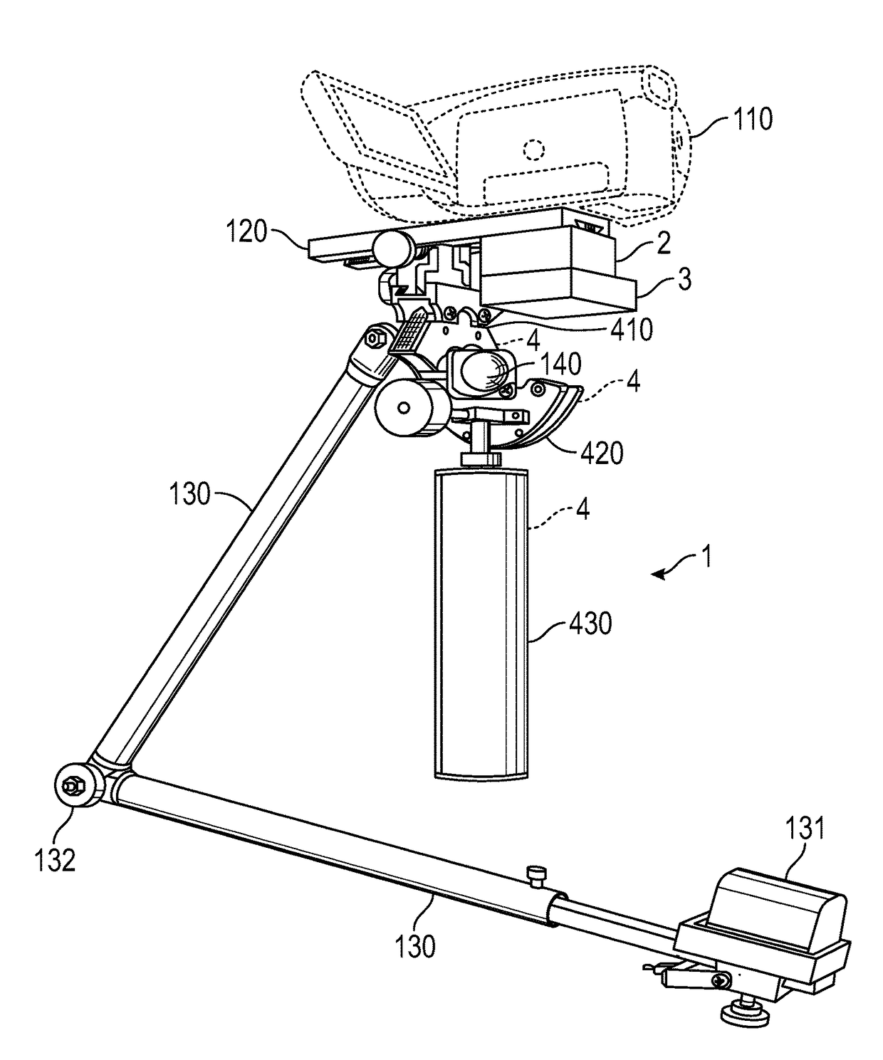
  • Actively stabilized payload support apparatus and methods
  • Actively stabilized payload support apparatus and methods
  • Actively stabilized payload support apparatus and methods

Examples


Embodiment Construction

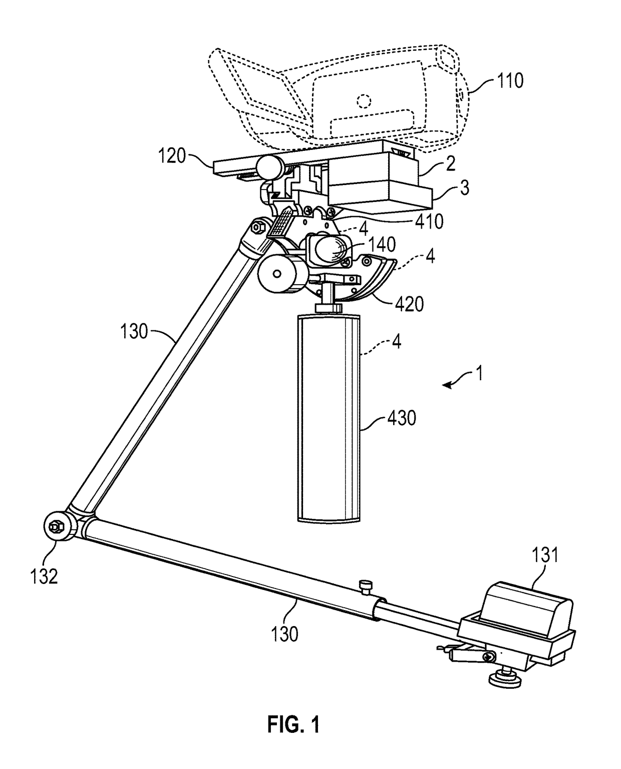
[0066]For simplicity, illustrative embodiments of the actively stabilized payload support will be described as they relate to a camera payload.

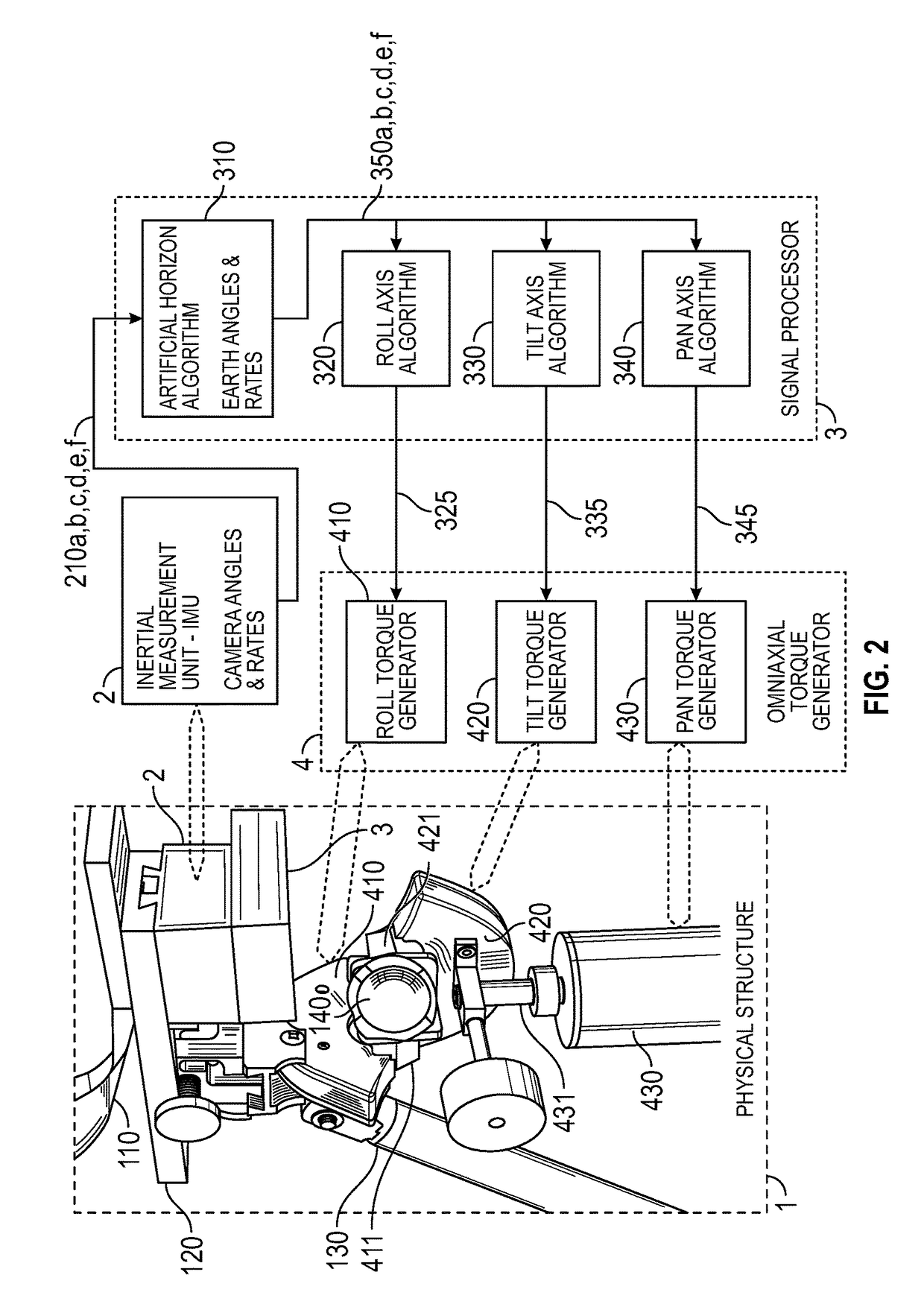
[0067]Illustrative embodiments of the actively stabilized payload support include an arrangement of interdependent sub-assemblies coupled in an interconnected continuous feedback loop fashion. In an illustrative embodiment, four possible sub-assemblies include:

1: Balanced Component Assembly

[0068]The balanced component assembly includes a “SLED” structure. An illustrative sled structure is described in U.S. Pat. No. 4,017,168, incorporated herein by reference, where it is designated as “equipment for use in hand held photography”. The sled structure will be referred to herein in an abbreviated manner as a rig or stabilizer. The stabilizer together with a payload, such as a camera and related equipment, will be referred to as a “balanced component assembly.”

[0069]FIG. 1 depicts a balanced component assembly according to an illustrative embodime...


PUM


Abstract

A payload stabilizer and methods for stabilizing a payload suitable for use with video camera payloads. The stabilizer has a feedback system providing supplemental torques to the payload through a gimbal.

Description

CROSS REFERENCE TO RELATED APPLICATIONS[0001]This application is a continuation-in-part of U.S. patent application Ser. No. 15 / 160,675, filed May 20, 2016, which is a continuation-in-part of U.S. patent application Ser. No. 14 / 267,500, filed May 1, 2014, which is a continuation-in-part of International Patent Application No. PCT / US2012 / 063298, filed Nov. 2, 2012, which claims the benefit of U.S. Provisional Patent Application No. 61 / 587,439, filed Jan. 17, 2012, and U.S. Provisional Patent Application No. 61 / 554,676, filed Nov. 2, 2011. This application also directly claims the benefit of U.S. Provisional Patent Application No. 62 / 165,461, filed May 22, 2015, and U.S. Provisional Patent Application No. 62 / 175,666, filed Jun. 15, 2015. The aforementioned applications are incorporated herein by reference.BACKGROUND OF THE INVENTION[0002]This invention relates generally to inertial stabilizing devices and to methods therefore, and is applicable to payloads such as, for example, image c...

Claims


Application Information

Patent Timeline
Patent Type & Authority Patents(United States)
IPC IPC(8): G03B17/56F16M11/18F16M13/04F16M11/10G02B27/64F16M13/00F16M11/20
CPCG03B17/563F16M11/105F16M11/18F16M11/2064F16M13/04G02B27/646G03B17/561F16M13/00F16M2200/044F16M2200/042
Inventor WAGNER, STEVEN D.BROWN, GARRETT W.HOLWAY, JERRY
Owner WAGNER STEVEN D
Why Eureka
Try Eureka