Powering a self-service terminal

a self-service terminal and power supply technology, applied in emergency power supply arrangements, instruments, transportation and packaging, etc., can solve the problems of inconvenience for customers, adversely affecting the reputation of respective banking establishments, and undesirable downtime of atms

Active Publication Date: 2018-03-20
NCR CORP
View PDF7 Cites 2 Cited by
  • Summary
  • Abstract
  • Description
  • Claims
  • Application Information

AI Technical Summary

Benefits of technology

[0007]It is an aim of certain embodiments of the present invention to provide a method and apparatus for powering an SST in an uninterruptable manner irrespective of the location of the SST, whilst reducing the overall cost of the SST, increasing the efficiency of energy conversion required by the SST, reducing the space required by the SST, and utilising a number of different power sources.
[0008]It is an aim of certain embodiments of the present invention to provide a method and apparatus for powering an SST whilst providing instantaneous power to the SST on demand, reducing the amount of heat loss during conversion of a power supply, and reducing the risk of downtime of the SST in the event of a loss or drop in the mains AC power supply.
[0049]Certain embodiments of the present invention may provide a method and apparatus for uninterruptedly powering an SST in a location where mains power loss and / or drops are commonplace.
[0050]Certain embodiments of the present invention may provide a method and apparatus for uninterruptedly powering an SST by utilising a number of different power sources in an efficient manner.

Problems solved by technology

However, in many locations around the world, such as developing countries, a mains power supply is often not available or is prone to frequent outages which result in undesirable downtime of the ATM, particularly if a back-up power supply is not available or insufficient.
Downtime of an ATM causes inconvenience to customers wanting to use the ATM and adversely affects the reputation of a respective banking establishment providing the ATM.
Furthermore, a conventional ATM includes an AC powered UPS which requires an inverter to convert a DC power supply from a number of back-up batteries into an AC power supply for the UPS when a mains AC power supply is not available or insufficient.
Conversion of power supplies is particularly inefficient and a significant amount of energy, particularly in the form of heat, is lost during such conversion.

Method used


Image

  • Powering a self-service terminal
  • Powering a self-service terminal
  • Powering a self-service terminal

Examples


Embodiment Construction

[0055]In the drawings like reference numerals refer to like parts.

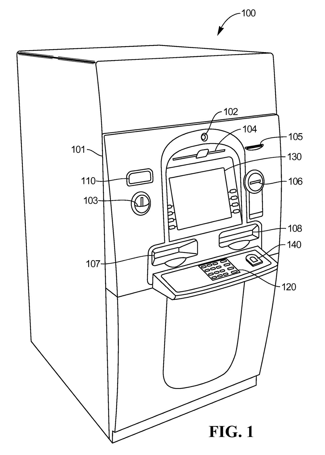
[0056]FIG. 1 illustrates a self-service cheque depositing terminal in the form of an image-based cheque depositing Automated Teller Machine (ATM) 100. It will be appreciated that certain embodiments of the present invention are applicable to a wide variety of terminals in which items of media such as cheques and / or currency notes and / or giros and / or lottery tickets and / or other such flexible sheet-like items of media are to be transported and directed in different directions. The type of terminal will of course be appropriate for the type of items of media being transported.

[0057]As illustrated in FIG. 1, the ATM 100 includes a fascia 101 coupled to a chassis (not shown). The fascia 101 defines an aperture 102 through which a camera (not shown) images a customer of the ATM 100. The fascia 101 also defines a number of slots for receiving and dispensing media items and a tray 103 into which coins can be dispensed. The s...


PUM


Abstract

The present invention provides a method and apparatus for powering a Self Service Terminal (SST), comprising a primary power supply, a back-up power supply, at least one renewable power supply, and a power management controller for selectively using the renewable power supply when a first power level is available from the renewable power supply, and to supplement or replace the renewable power supply with the primary power supply and / or the back-up power supply when a second power level is required by the SST that exceeds the first power level.

Description

FIELD OF THE INVENTION[0001]The present invention relates to powering a Self-Service Terminal (SST) and, in particular but not exclusively, to a method and apparatus utilising a number of different power sources for supplying power to an SST in an uninterruptable manner.[0002]A typical SST includes an Automated Teller Machine (ATM) which presents one or more bank notes to a customer in response to a customer transaction at the ATM. A conventional ATM requires a power supply for it to effectively operate in all modes of operation, such as dormant or idle when in a standby mode of operation and active when a transaction is being made at the ATM.[0003]Conventional ATMs are powered by a mains AC power supply which is provided by the Grid. Conventional ATMs are often also provided with a back-up power supply or a so-called uninterruptable power supply (UPS) which includes a number of batteries that are used to either boost the mains power supply or to replace the mains power supply in th...

Claims


Application Information

Patent Timeline
Patent Type & Authority Patents(United States)
IPC IPC(8): H02J7/00G06Q40/02H02M7/04H02J9/06H02J7/35H02J9/00
CPCH02J9/06G06Q40/02H02J7/35H02M7/04Y10T307/625Y02B10/72Y10T307/615Y10T307/62Y02B10/70Y04S10/50
Inventor MACINNES, DONALDHENDERSON, JAMES
Owner NCR CORP
Why Eureka
Try Eureka