
Bird deterrent

a technology of deterrent and deterrent layer, applied in the field of deterrent layer, can solve the problems of high replacement cost, health, environmental and aesthetic problems, rapid wear of deterrent layer,

Active Publication Date: 2018-03-27
DAMBRA DOMENICO
View PDF17 Cites 2 Cited by
  • Summary
  • Abstract
  • Description
  • Claims
  • Application Information

AI Technical Summary

Benefits of technology

The deterrent effectively keeps birds away without physical harm, maintains hygiene, and is resistant to atmospheric agents, reducing maintenance and replacement costs while protecting gutters from leaves.

Problems solved by technology

It is widely known the health, environmental and aesthetic problem caused by defecation of birds in the cities.
Furthermore, the repeated exposure to the atmospheric agents and defecation of the birds themselves leads to a rapid wear of the deterrent, thus causing high replacement costs.
In addition to this is the fact that the electrical deterrents imply high costs of manufacture, installation and maintenance.

Method used


Image

  • Bird deterrent
  • Bird deterrent
  • Bird deterrent

Examples


first embodiment

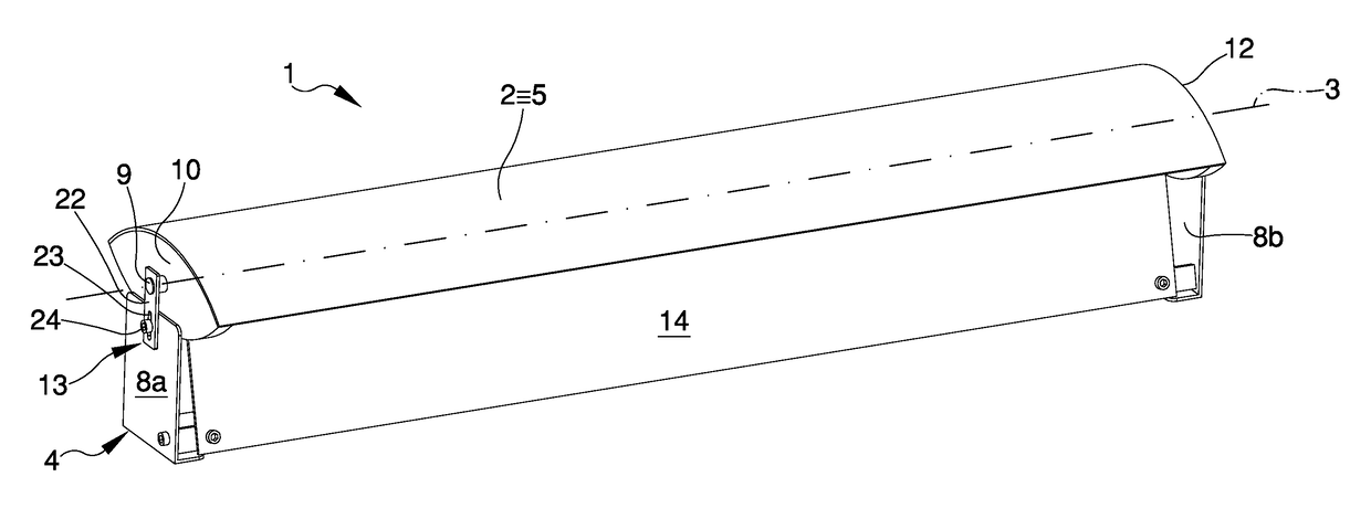
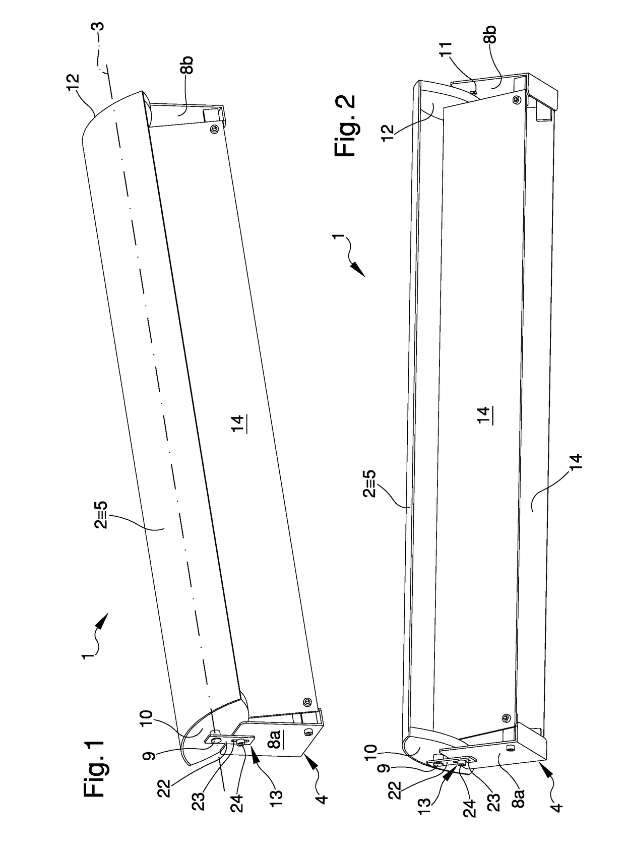
[0014]FIG. 1 is an axonometric view of the bird deterrent according to the invention in a first embodiment;

[0015]FIG. 2 is an axonometric front view and from below of the bird deterrent according to the invention in a first embodiment;

second embodiment

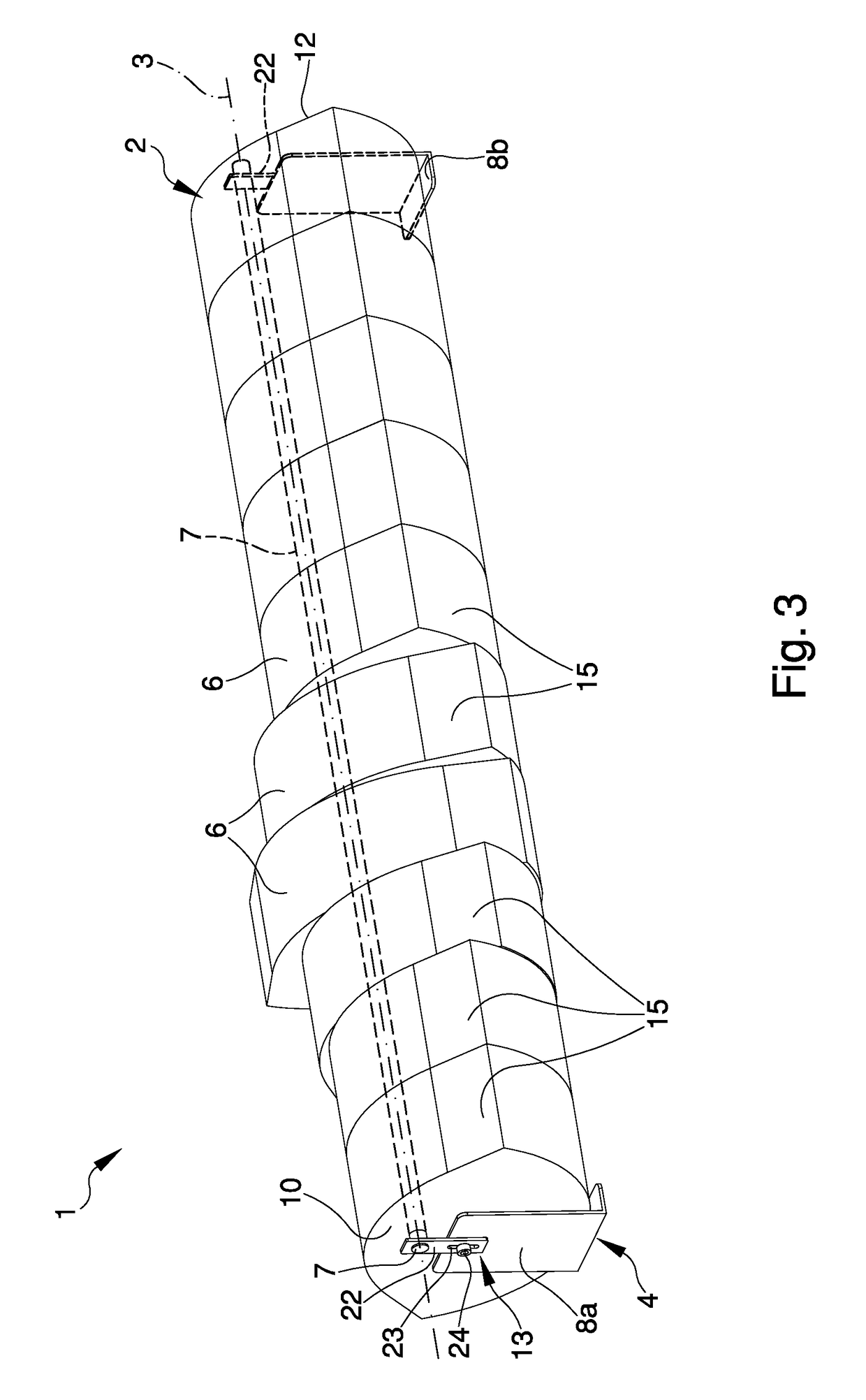
[0016]FIG. 3 is an axonometric view of the bird deterrent according to the invention in a second embodiment;

third embodiment

[0017]FIG. 4 is an axonometric view of the bird deterrent according to the invention in a third embodiment;

[0018]FIG. 5 is an exploded view of the deterrent of FIG. 4.


PUM


Abstract

The bird deterrent comprises a substantially flat tilting surface, having a substantially elongated shape and a substantially curvilinear profile, which can be positioned in a balancing position and oscillating, as a consequence of a bird or the like perching on it, around at least an axis of rotation substantially horizontal and parallel to the longitudinal axis of the tilting surface, and support means associable with a perching surface and supporting the tilting surface.

Description

TECHNICAL FIELD[0001]The present invention relates to a bird deterrent.BACKGROUND ART[0002]It is widely known the health, environmental and aesthetic problem caused by defecation of birds in the cities.[0003]Mechanical deterrents are being used to date comprising different embodiments, including “hedgehog” or spring steel structures which can be positioned on the external surfaces of houses, schools, hospitals and artworks.[0004]Moreover, electrical deterrents are known powered by a control unit and operating by releasing low voltage micro-shocks able to keep the birds away from the pre-established area.[0005]These deterrents of known type do have however some drawbacks.[0006]In fact, the mechanical deterrents are in many cases used by the birds as a support for nesting, thereby greatly boosting the hygienic and aesthetic problem.[0007]Furthermore, the repeated exposure to the atmospheric agents and defecation of the birds themselves leads to a rapid wear of the deterrent, thus caus...

Claims


Application Information

Patent Timeline
Patent Type & Authority Patents(United States)
IPC IPC(8): A01M29/00A01M29/32E04D13/00
CPCE04D13/004A01M29/32
Inventor DAMBRA, DOMENICO
Owner DAMBRA DOMENICO
Learn More