System and method for designing wavefront-guided ophthalmic lenses

a wavefront-guided, ophthalmic lens technology, applied in the field of vision care, can solve the problems of non-reversible surgical methods, limited availability, and inapplicable methods, and achieve the effect of accurate measurement of ocular aberration and reliably achieving vision correction

Active Publication Date: 2018-03-27
UNIVERSITY OF ROCHESTER
View PDF19 Cites 9 Cited by
  • Summary
  • Abstract
  • Description
  • Claims
  • Application Information

AI Technical Summary

Problems solved by technology

However, it is an impractical method.
Although refractive surgery has been proven to be practical and effective to correct the aberration, it is a non-reversible surgical method, and its availability is restricted by factors such as corneal thickness and the amount of the aberration.
However, such vision correction still has its limits.

Method used


Image

  • System and method for designing wavefront-guided ophthalmic lenses
  • System and method for designing wavefront-guided ophthalmic lenses
  • System and method for designing wavefront-guided ophthalmic lenses

Examples


Embodiment Construction

[0013]A preferred embodiment of the present invention will be set forth in detail with reference to the drawings, in which like reference numerals refer to like elements or steps throughout.

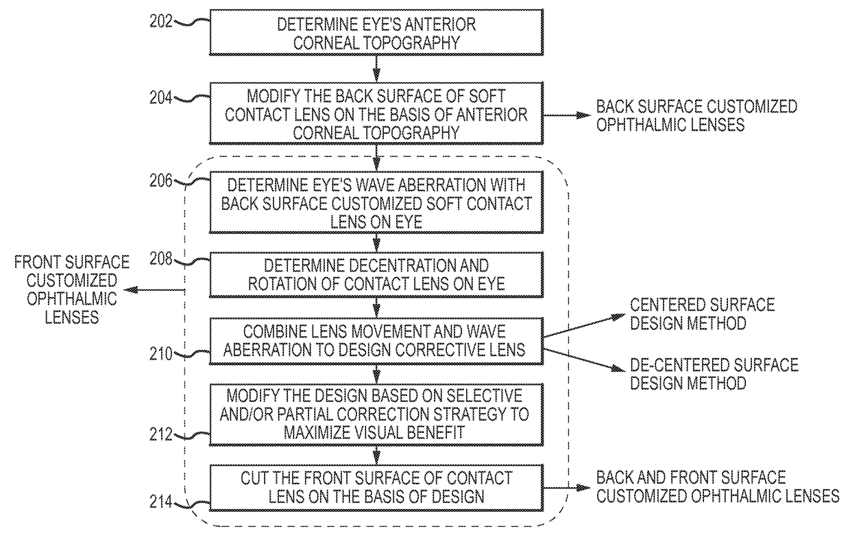
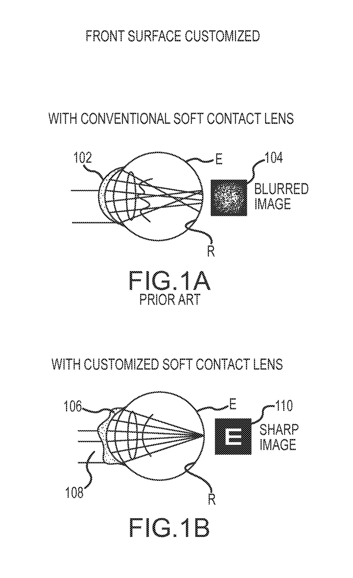
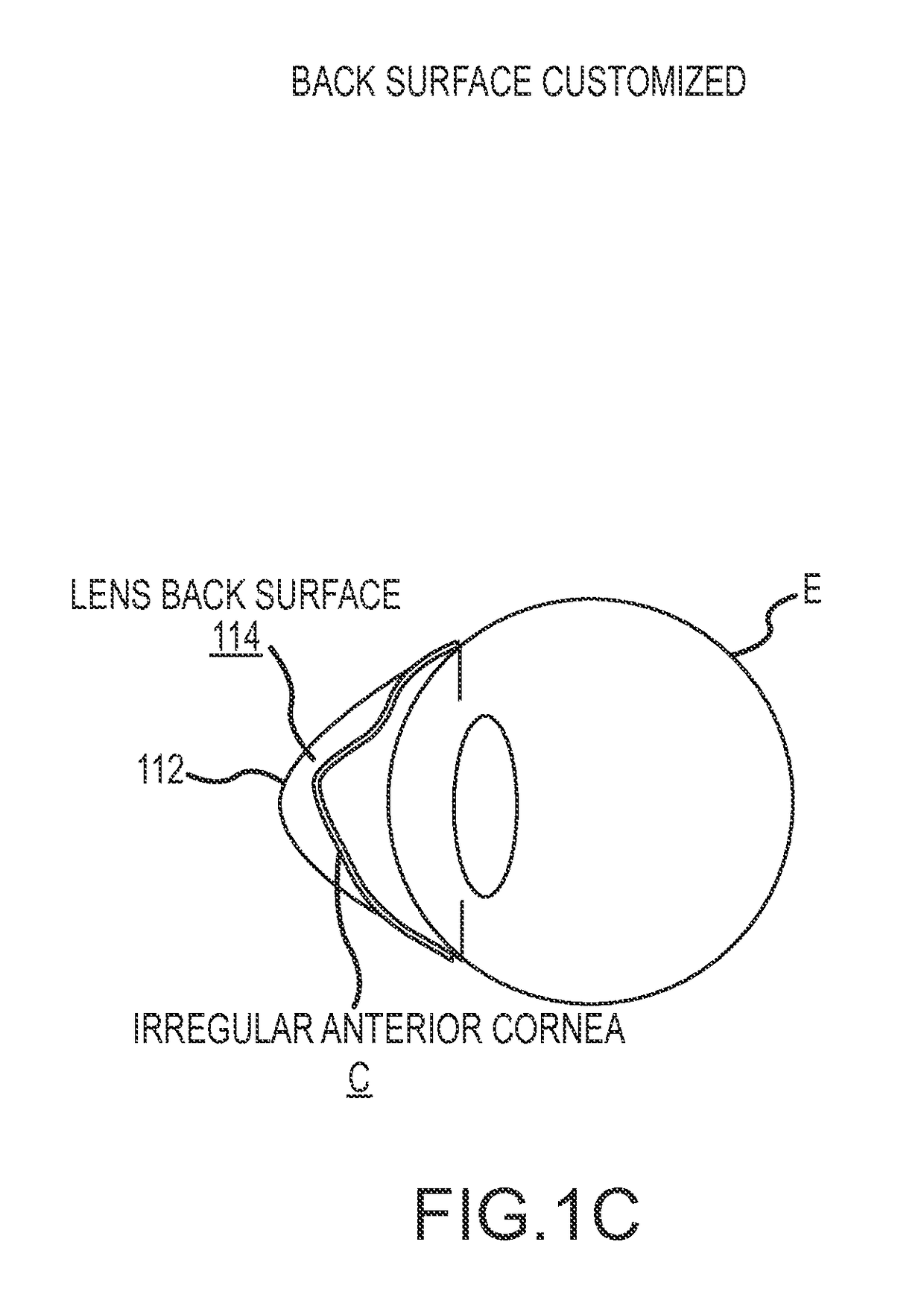
[0014]FIGS. 1A-1C illustrate the concept of customized ophthalmic lenses. As shown in FIG. 1A, a conventional lens 102 applied to the patient's eye E provides only a spectacle prescription, leaving the irregular higher-order aberrations uncorrected. That leads to a blurred image 104 on the retina R, especially for larger pupils and eyes with corneal abnormalities such as keratoconus and corneal transplants. As shown in FIG. IB, a front-surface-customized ophthalmic lens 106 with an asymmetric surface profile 108 on the front side of the lens 106 corrects those higher-order aberrations to provide a sharp image 110.

[0015]In eyes with abnormal corneas, lens movements impair the correction performance, since the optical axis of the corrective lens is not aligned with the eye's optical axis. In order ...


PUM


Abstract

The design of a corrective lens combines the measured aberration with decentration and rotation of the lens to design customized optical surface profiles to reliably achieve vision correction.

Description

REFERENCE TO RELATED APPLICATIONS[0001]The present application is a continuation of International Patent Application No. PCT / US2013 / 022507, filed Jan. 22, 2013, entitled SYSTEM AND METHOD FOR DESIGNING WAVEFRONT-GUIDED OPHTHALMIC LENSES, which claims the benefit of U.S. Provisional Patent Application No. 61 / 588,956, filed Jan. 20, 2012, each of the foregoing applications being incorporated by reference in its entirety.FIELD OF THE INVENTION[0002]The present invention is directed to vision care and more particularly to higher-order aberration correcting / inducing ophthalmic lenses to improve visual performance.DESCRIPTION OF RELATED ART[0003]It has been well known that the human eye suffers from the optical defects called “wavefront aberrations,” which include both lower (defocus and astigmatism) and higher order aberrations (those of higher order than defocus and astigmatism). Optical and psychophysical tests have demonstrated that correcting those aberrations significantly improves ...

Claims


Application Information

Patent Timeline
Patent Type & Authority Patents(United States)
IPC IPC(8): G02C3/00A61B3/00A61F2/14G02C7/04A61F2/16G02C7/00G02C7/02
CPCA61F2/145A61B3/0025A61F2/1637G02C7/028G02C7/047G02C7/027G02C2202/22A61F2240/002
Inventor YOON, GEUNYOUNG
Owner UNIVERSITY OF ROCHESTER
Why Eureka
Try Eureka