Sawing beads and method for making the same

a technology of manufacturing method and sawing bead, which is applied in the field of sawing bead manufacturing, can solve problems such as negatively affecting performance, and achieve the effect of good or better sawing performance and low diamond degradation

Inactive Publication Date: 2018-04-03
NV BEKAERT SA
View PDF16 Cites 0 Cited by
  • Summary
  • Abstract
  • Description
  • Claims
  • Application Information

AI Technical Summary

Benefits of technology

[0032]Particularly preferred are sleeves made by metal injection molding as described in the application PCT / EP2013 / 073905 of the current applicant. Such a process allows a large degree of freedom to shape the inner part of the sleeve. In addition such a sleeve shows a favorable surface roughness for easy coupling of the laser light into the sleeve material.
[0038]There are many known alloys of metal matrix materials that are suitable for laser cladding. Given the constraints imposed by the abrasive particles alloys with liquidus temperatures between 400° C. and 1100° C. are more preferred. These alloys comprise silver, copper, nickel or cobalt as main alloy element. Additionally, melting temperature reducing elements such as tin, zinc, or even indium can be added. In the case of nickel non-metals like phosphorous, silicon or boron can be used to reduce the liquidus temperature.
[0041]They are known to improve the wetting of abrasive particles during deposition and;
[0047]Possibly filler materials can be added to the metal matrix material to fine tune the wear of the metal matrix material. Popular filler materials are hard ceramics such as tungsten carbide, silicon carbide, aluminium oxide and zirconium oxide. Addition of the aforementioned fillers will result in a more wear resistant metal matrix material and allows to synchronise the wear of the abrasive particles with that of the metal matrix material.
[0057]The supply of diamond particles may follow the same feed channel as the supply of metal matrix material. Alternatively the supply of diamonds may follows a separate supply channel possibly supported by means of a gas flow or alternatively by strewing. The supply sequence of diamonds is preferably separately controllable from the supply of metal matrix material. In this way initially metal matrix material can be supplied without diamonds while diamonds can be fed once the molten metal pool has formed.
[0070]It is the experience of the inventors that the adjustment to the laser power is minimal when the sequence of laser illumination and powder feeding are well synchronised by positioning the laser spot relative to the powder feed in an optimal way. This is achieved by optically spreading the laser beam that irradiates the metal sleeve or already formed bead surface into a first substantially elongated area spot (e.g. ellipsoidal or rectangular) that spans about the axial length of the metal sleeve or already formed bead surface. The supply of metal matrix material arrives at the surface of the metal sleeve or already formed bead surface in a second substantially elongated area, also spanning about the length of the metal sleeve but having an area that is smaller than said first area. By preference the supply of metal matrix powder and diamonds is focused on the molten metal pool to prevent spill-over of the diamond particles.

Problems solved by technology

Further sawing beads are defined that may show some diamond damage but not enough to affect performance negatively.

Method used


Image

  • Sawing beads and method for making the same
  • Sawing beads and method for making the same
  • Sawing beads and method for making the same

Examples


Embodiment Construction

[0091]In a series of experiments laser cladded beads were made on mild steel cylindrical sleeves of length 11 mm, having an outer diameter of 5.00 mm and a wall thickness of 0.575 mm.

[0092]The following type of equipment was used:[0093]Laser cladding system[0094]Diodelaser ‘Laserline LDF 3 kW’ operating at 1900 W in continuous mode at wavelengths of 808 and 940 μm.[0095]A lateral feed channel for feeding metal matrix powder and diamond, the diamond being separately controllable from the metal matrix powder flow;[0096]Powder handling equipment:[0097]Sulzer Metco Twin powder hopper[0098]Gas supply: argon.[0099]Both metal matrix material and diamond particles were fed through the same argon gas flow.

[0100]As a metal matrix material powder obtained from Phoenix Scientific Industries Ltd. of composition Cu—Sn (13 wt %)—Ti (9 wt %) was used. Differential Scanning Calorimetric analysis revealed that solid-solid phase transitions start to occur at about 765° C. and that the powder completel...


PUM

PropertyMeasurementUnit
temperatureaaaaaaaaaa
mean sizeaaaaaaaaaa
temperatureaaaaaaaaaa

Abstract

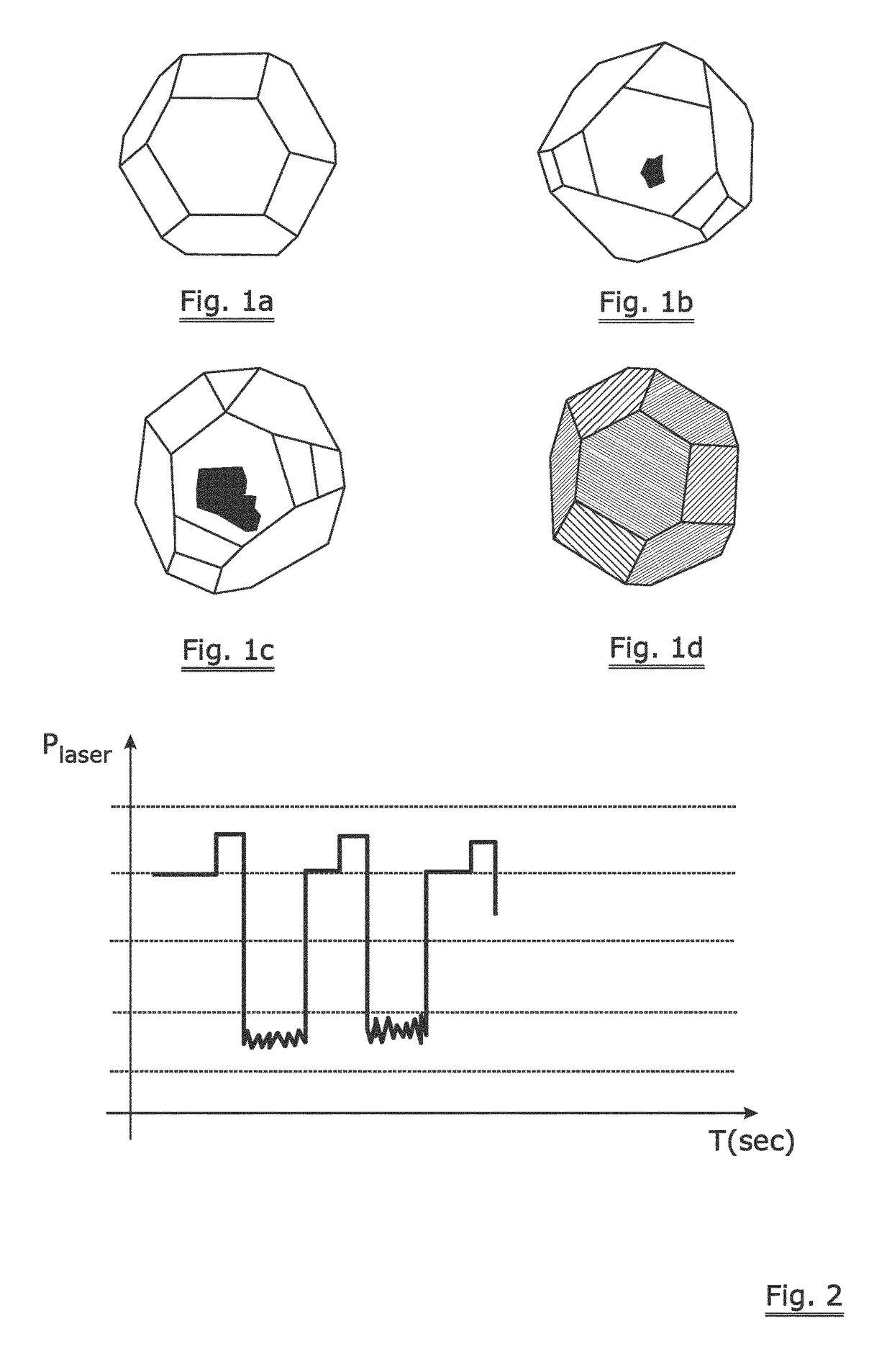
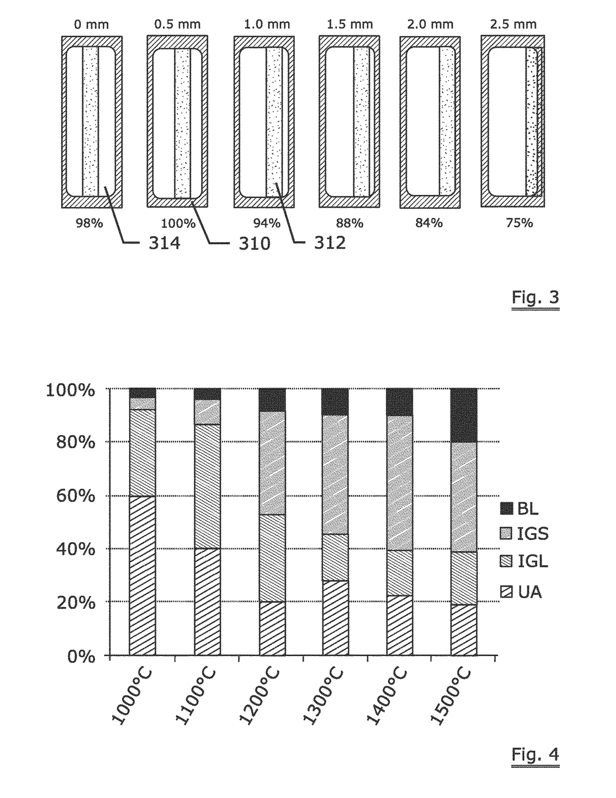
A method to make sawing beads by means of laser cladding is disclosed whereby metal matrix powder is molten by means of a laser beam on a rotating sleeve while diamonds are thrown in the molten metal pool. By carefully controlling the temperature of the molten metal pool at or above 1150° C. for less than 200 ms the internal graphitization of the diamonds can be limited. Although some of the diamonds in the sawing bead show internal graphitization it is demonstrated by the inventors that a sawing cord using the bead obtained by the method has an above standard sawing performance.

Description

TECHNICAL FIELD[0001]The invention relates to the manufacturing of a sawing bead for use on a sawing cord for sawing natural or artificial stones or materials. Further the invention relates to the sawing bead thus obtained and the sawing cord equipped with such beads.BACKGROUND ART[0002]Sawing cords are increasingly used to saw blocks of stone into slabs for architectural or home interior use. The types of material sawn have steadily increased from the softer metamorphic stones such as marble to the extremely hard igneous rocks like granite (in all its shades of hardness and origin). In a saw machine using a sawing cord the cord is tensioned between at least two pulleys of which at least one is driven while the cord is pushed through a stone. ‘Sawing wire’ or ‘saw wire’ is many times used as an alternative term for ‘sawing cord’ but in this application the latter is preferred as it discriminates the product from other saw tools that are based on a single filament. A cord is known to...

Claims


Application Information

Patent Timeline
Patent Type & Authority Patents(United States)
IPC IPC(8): B28D1/12B23D61/18B23D65/00
CPCB28D1/124B23D65/00B23D61/185B23D61/18
Inventor VANEECKE, JANBAEKELANDT, TOMGROENEN, ROLAND
Owner NV BEKAERT SA
Why Eureka
Try Eureka