
Bicycle security device

a technology for security devices and bicycles, applied in anti-theft cycle devices, cycle equipment, lock applications, etc., can solve the problems of multiple locks, difficult to recover bicycles and identify, and difficulty in riding or carrying bicycles, and achieve the effect of convenient and convenient way to lock bicycles

Active Publication Date: 2018-04-03
LINKA GRP LTD
View PDF13 Cites 6 Cited by
  • Summary
  • Abstract
  • Description
  • Claims
  • Application Information

AI Technical Summary

Benefits of technology

The invention provides an easy and convenient way to lock a bicycle by using a housing with a locking ring and an actuator component that engages with gear teeth on the locking ring. The housing can also have a communication electronics component to generate an indication for the actuator and a sound generation component to alert to tampering or motion. The locking device can also have an accelerometer electronics component to detect motion and activate the sound generation component. The locking device can also include a mounting bracket that securely attaches the lock to the bike frame, a GPS receiver, a lamp for illuminating either forward or backward, and a remote controller for wireless communication with the lock.

Problems solved by technology

However, once the lock or anchor is broken, the bicycle can be ridden or carried away.
Once removed, it is often difficult to recover the bicycle and identify the person taking the bike.
However, this has the disadvantage of having to carry multiple locks, the weight of the multiple locks, and having to remember keys and lock combinations for multiple locks.
Further, it can be time consuming setting up and unlocking each lock.

Method used


Image

  • Bicycle security device
  • Bicycle security device
  • Bicycle security device

Examples


operational example

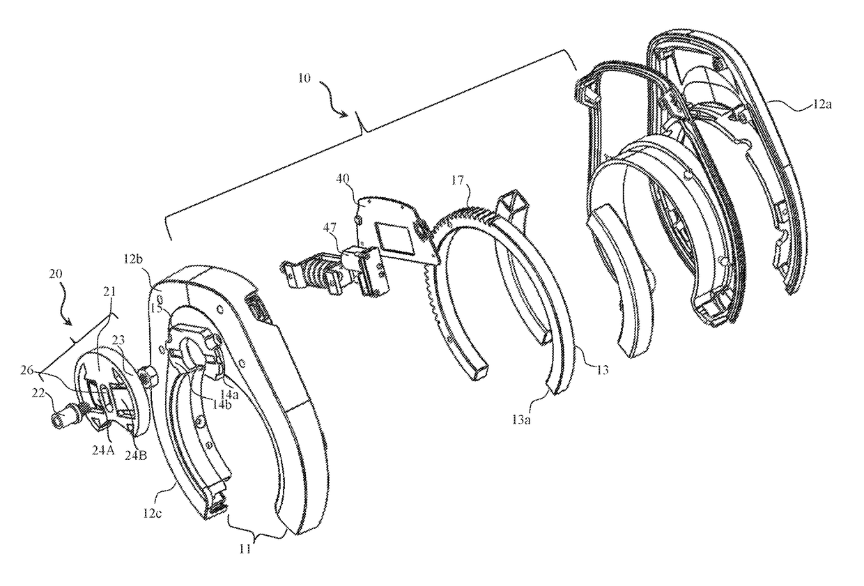
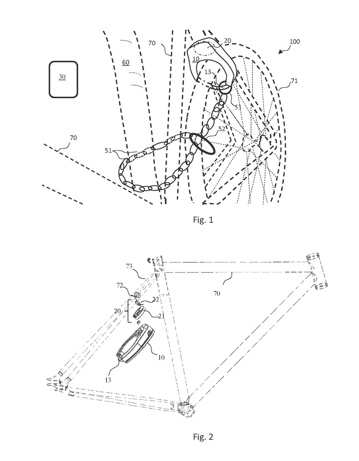
[0055]In operation, the locking device 10 has to be first installed on the bicycle 70. First the bracket 21 needs to be coupled to frame 73 of the bicycle 70. Preferably, the bracket 21 is coupled to frame 73 of the bicycle 70 using the bike frame anchor hole 72. A specially designed anchor bolt 22 is required to accommodate the bike brake and the locking device 10. Once the bracket 21 is mounted to the bicycle 70, the rear wheel 71 is removed.

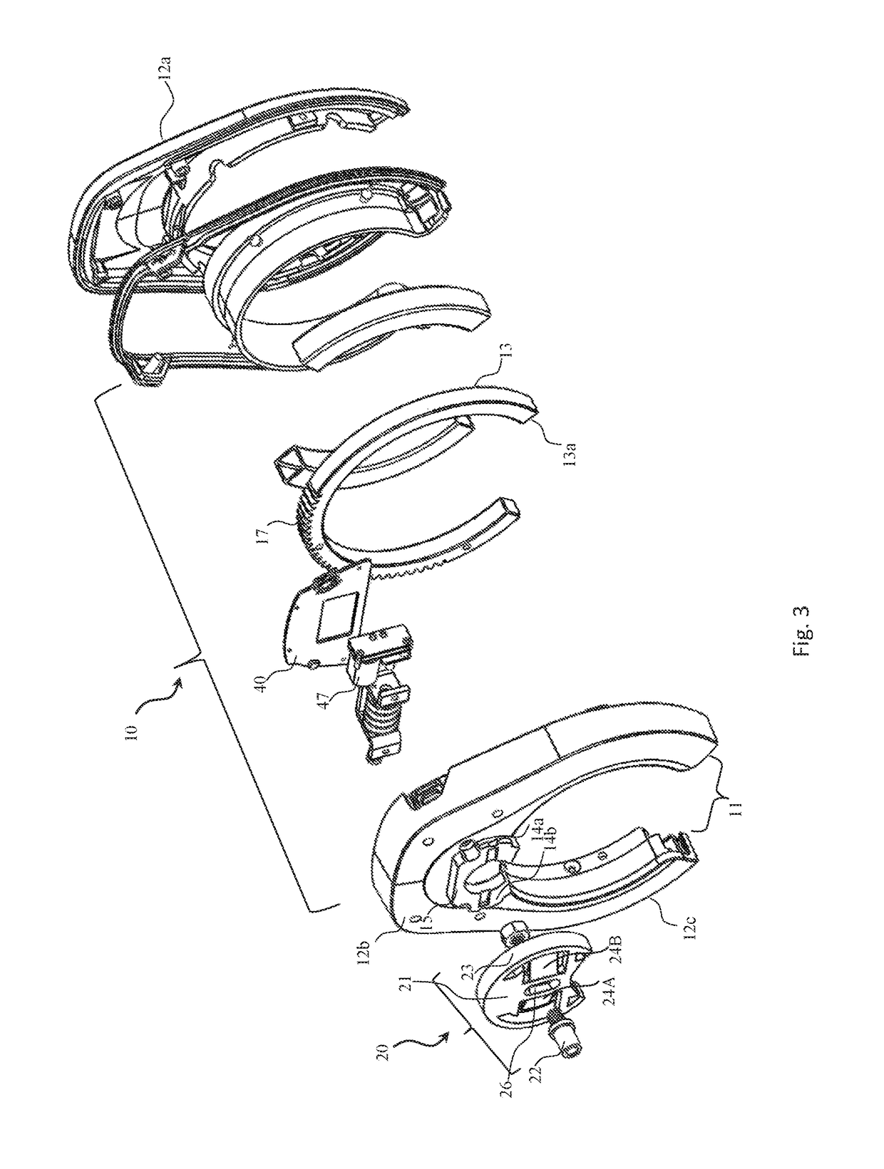
[0056]The next step is to couple the locking device 10 to the bracket 21. The back of the rear casting 12b is configured with the lock flange 15 with two horizontally orientated flange tabs 14a, 14b. The flange tabs 14a, 14b extends from the center of the lock flange 15 along a radial line through the center of the lock flange 15. The locking device 10 is held substantially perpendicular to plane of the wheel 71 and slid over the mounting bracket 20. The mounting bracket 20 has two mount tabs 24a, 24b located approximately one hundred and eigh...


PUM


Abstract

A bicycle locking device coupled to a bicycle and configured to prevent a wheel from turning. The locking device is configured with a transceiver to communicate with a remote device to receive locking and unlocking indications, and to transmit tampering indications to the remote device. The locking device can generate an audible sound when tampering is detected.

Description

FIELD OF INVENTION[0001]The present invention relates to security devices for bicycles or other vehicles having spoke wheels, or wheels having openings through which a security bar can pass through. More particularly, the present invention is in the field of bicycle locking devices.[0002]What is needed are locking devices and systems that can connect to the frame of a bicycle, that lock the drive train of the bicycle, that can give a visual indication to people of the locking device, and that can send a remote indication to a person of the opening or tampering with the locking device or bicycle.BACKGROUND[0003]Current bicycle locks prevent a bicycle from being removed from an anchor. However, once the lock or anchor is broken, the bicycle can be ridden or carried away. Once removed, it is often difficult to recover the bicycle and identify the person taking the bike.[0004]To minimize the likelihood of theft, people have concurrently used multiple types of conventional bicycle locks....

Claims


Application Information

Patent Timeline
Patent Type & Authority Patents(United States)
IPC IPC(8): E05B71/00E05B47/02B62H5/14E05B39/00E05B47/00E05B45/06B62H5/20B62J99/00
CPCE05B71/00B62H5/141B62H5/147B62H5/20E05B39/00E05B39/005E05B47/0001E05B47/0012E05B47/023E05B45/06E05B2047/0067B62J2099/002B62J2099/0013B62J45/20B62J45/412B62J45/414
Inventor MOHAMED, MOHAMED
Owner LINKA GRP LTD
Learn More