Exhaust gas purifying device

a technology of exhaust gas and purification device, which is applied in the direction of machines/engines, physical/chemical process catalysts, separation processes, etc., can solve the problems of large unevenness in the trapping region of particulate matter, blockage of the cells of the end face central region, and uneven flow of exhaust gas. , to achieve the effect of efficiently purifying the exhaust gas and removing particulate matter

Active Publication Date: 2018-04-03
NGK INSULATORS LTD
View PDF14 Cites 6 Cited by
  • Summary
  • Abstract
  • Description
  • Claims
  • Application Information

AI Technical Summary

Benefits of technology

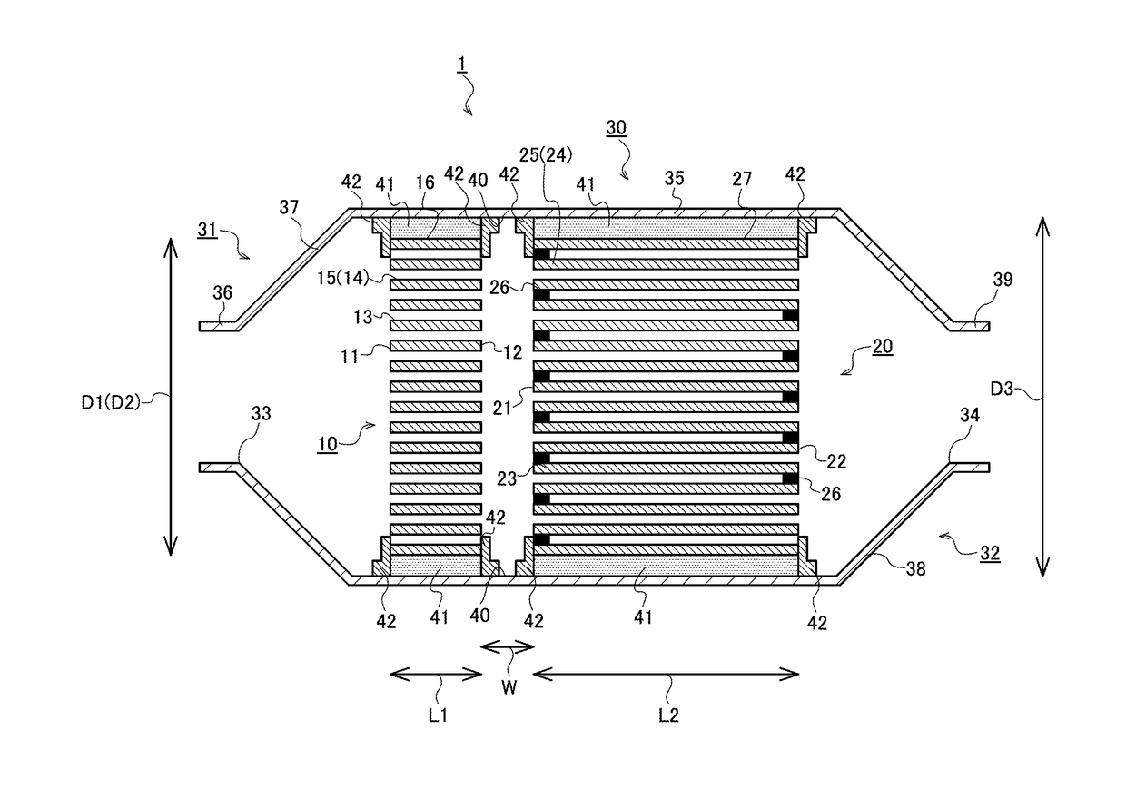
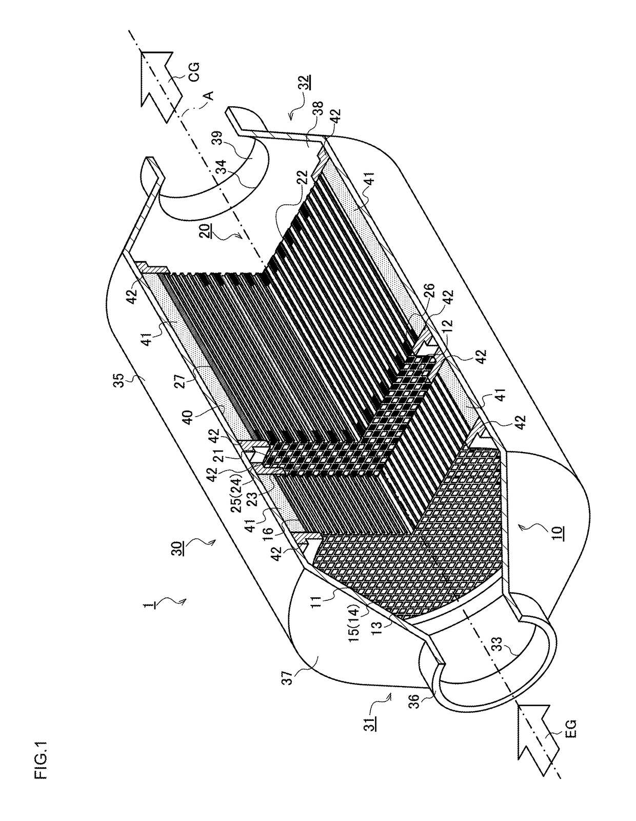
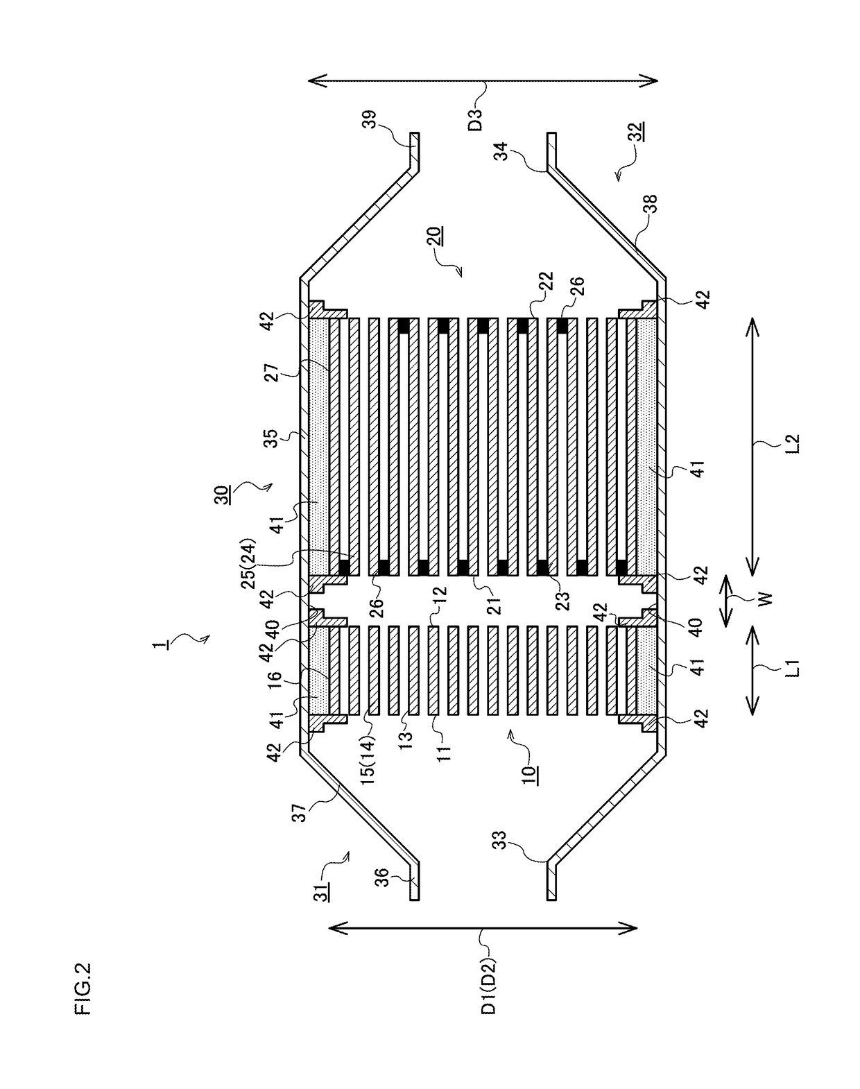
[0013]When the above-mentioned exhaust gas purifying device described in Patent Document 2 is used, an exhaust gas emitted from a direct injection type gasoline engine can efficiently be purified and treated by utilizing a trapping filter in which a honeycomb structure is used. In this exhaust gas purifying device, a honeycomb catalyst body onto which a three-way catalyst is loaded is further disposed at a position on an upstream side of a plugged honeycomb structure in which parts of cells are plugged, and for the purpose of decreasing a heat capacity of the honeycomb catalyst body, there is used a thin plate-shaped honeycomb catalyst body in which a length in a cell central axis direction is shorter than that of the plugged honeycomb structure.
[0017]Thus, the present invention has been developed in view of the above actual circumstances, and an object thereof is to provide an exhaust gas purifying device in which an exhaust gas emitted from a direct injection type gasoline engine evenly flows into end faces of a plugged honeycomb structure and a honeycomb catalyst body and which is capable of stabilizing a purifying efficiency of a particulate matter and efficiently purifying the exhaust gas.
[0031]According to an exhaust gas purifying device of the present invention, there can be varied pressure losses due to an exhaust gas in an end face central region and / or an end face circumferential region in a second inflow side end face and a second outflow side end face of a second honeycomb substrate disposed in a plugged honeycomb structure, respectively. Further specifically, the pressure loss in the vicinity of the end face central region can be larger than the pressure loss of the end face circumferential region, the exhaust gas can be inhibited from unevenly flowing into an end face central region of a honeycomb catalyst body and the end face central region of the plugged honeycomb structure, and the exhaust gas can uniformly flow through a first inflow side end face and / or a first outflow side end face and the second inflow side end face and / or the second outflow side end face. In consequence, it is possible to efficiently remove a particulate matter included in the exhaust gas and to efficiently purify the exhaust gas.

Problems solved by technology

That is, in the exhaust gas purifying device, unevenness occurs in the flow of the exhaust gas.
In this way, large unevenness occurs in the trapping regions of the particulate matter.
Thus, the particulate matter is easily deposited on partition walls of cells of the end face central region, and by a purifying treatment of the particulate matter over a long period of time, there might be caused a defect that the cells of the end face central region are clogged.
Furthermore, due to the deposition of the particulate matter, a pressure loss might increase.
Therefore, there might occur the problem that a purifying efficiency and a purifying performance of the particulate matter in the exhaust gas purifying device remarkably deteriorate.
Consequently, in an effective cross section of the honeycomb catalyst body, there occurs the problem that the exhaust gas is not efficiently purified.

Method used


Image

  • Exhaust gas purifying device
  • Exhaust gas purifying device
  • Exhaust gas purifying device

Examples


examples

[0103]Table 1 mentioned below shows a summary of a diameter, a length, L1 / D1, a cell density, a partition wall thickness, a porosity, pore diameters and a catalyst loading ratio of a honeycomb catalyst body, a diameter, a length, L1 / L2, a cell density, a partition wall thickness, a porosity, pore diameters, an arrangement standard and a catalyst loading ratio of a plugged honeycomb structure, and a distance between the honeycomb catalyst body and the plugged honeycomb structure (a distance between carriers) in each of Examples 1 to 18 and Comparative Example 1 of an exhaust gas purifying device of the present invention.

[0104]Comparative Example 1 indicates the exhaust gas purifying device using a plugged honeycomb structure constituted in a conventional arrangement standard pattern in which plugging portions are alternately arranged. Furthermore, Example 1 and Examples 7 to 17 indicate the exhaust gas purifying devices in each of which plugging portions are arranged in accordance wi...


PUM

PropertyMeasurementUnit
thicknessaaaaaaaaaa
distanceaaaaaaaaaa
length L1aaaaaaaaaa

Abstract

An exhaust gas purifying device includes a honeycomb catalyst body, a plugged honeycomb structure and a can member to receive therein the honeycomb catalyst body and the plugged honeycomb structure, and the plugged honeycomb structure disposed at a position on a downstream side of the honeycomb catalyst body is designed so that a pressure loss in an end face central region of at least one of a second inflow side end face and a second outflow side end face of a second honeycomb substrate is larger than a pressure loss of an end face circumferential region positioned around the end face central region.

Description

[0001]The present application is an application based on JP 2015-185814 filed on Sep. 18, 2015, JP2016-090014 filed on Apr. 28, 2016 and JP2016-152169 filed on Aug. 2, 2016 with Japan Patent Office, the entire contents of which are incorporated herein by reference.BACKGROUND OF THE INVENTION[0002]Field of the Invention[0003]The present invention relates to an exhaust gas purifying device, and more particularly, it relates to an exhaust gas purifying device which is capable of efficiently removing particulates in an exhaust gas emitted from a direct injection type gasoline engine and efficiently purifying the exhaust gas.[0004]Description of the Related Art[0005]In recent years, to meet activation of environmental protection movement and various requirements for resource saving, energy saving and the like, there has been advanced the development of an engine which is excellent in fuel economy performance and enables long-distance and long-time running in a state where consumption of ...

Claims


Application Information

Patent Timeline
Patent Type & Authority Patents(United States)
IPC IPC(8): F01N3/20B01D53/94F01N3/022F01N13/00B01D46/24F01N3/28B01J35/04
CPCF01N3/2842B01D46/2422B01D46/2429B01D46/2459B01D46/2462B01D53/94B01D53/944B01J35/04F01N3/0222F01N3/2828F01N13/0097B01D46/247Y02T10/22B01D53/9454B01D2046/2433B01D2046/2481B01D2255/915B01D2255/9202B01D2255/9205F01N2240/20F01N2330/48F01N2330/60F01N2340/02F01N2470/02Y02T10/20F01N3/035B01D46/2478B01D46/24491B01D46/2484B01D46/2482B01D46/2476Y02T10/12B01D46/2474
Inventor AOKI, TAKASHI
Owner NGK INSULATORS LTD
Why Eureka
Try Eureka