
Mounting assembly

a technology of mounting assembly and mounting plate, which is applied in the direction of cameras, lock casings, coupling device connections, etc., can solve the problems of loose arrangement, difficult to achieve tight arrangement, and need to make tight arrangement very strong, and achieve strong tightening

Active Publication Date: 2018-04-10
AXIS
View PDF20 Cites 3 Cited by
  • Summary
  • Abstract
  • Description
  • Claims
  • Application Information

AI Technical Summary

Benefits of technology

[0010]It is an object of the present invention to provide a mounting assembly for an electronic device, wherein an arm of the mounting assembly is lockable relative a base of the mounting assembly in an improved manner. It is a further object of the present invention to provide a locking mechanism that is robust and strong without requiring unreasonable high level of tightening and preferably being independent of the materials used in the mounting assembly.
[0011]It is a further object of the present invention to provide a locking mechanism that can be combined with the usage of conductive materials of the parts to be locked for achieving a conductive path through the construction.

Problems solved by technology

One problem with this type of arrangement is that the tight arrangement of the parts may need to be made very strong in order to achieve a sufficient friction force.
Such a tight arrangement may be difficult to achieve and there is a risk that the arrangement come loose over time.
This may be a difficult problem to overcome when using certain types of sleek materials of the parts.
A problem with friction-increasing materials is that they may be difficult to apply to certain material surfaces and a high level of quality control may be required.
Moreover, the friction-increasing material may wear off over time which is difficult to both discover and take care of since the interface is typically not visible without disassembling the mounting assembly.
In addition, in mounting assemblies where it is desirable to provide a conducting path between the arm and the base, to for example fulfill EMC regulations, the friction-inducing material provides an undesired nonconductive barrier which may obstruct the conducting path.
An unlimited rotational movement of the parts relative each other may cause a problem in that the cable may be twisted beyond function, be sheared off, or a continuous rotation may dislodge connectors thereof.

Method used


Image

  • Mounting assembly
  • Mounting assembly
  • Mounting assembly

Examples


Embodiment Construction

[0040]The present invention will now be described more fully with reference to the accompanying drawings, in which currently preferred embodiments of the invention are shown. The invention may however be embodied in many different forms and should not be construed as limited to the embodiments set forth herein.

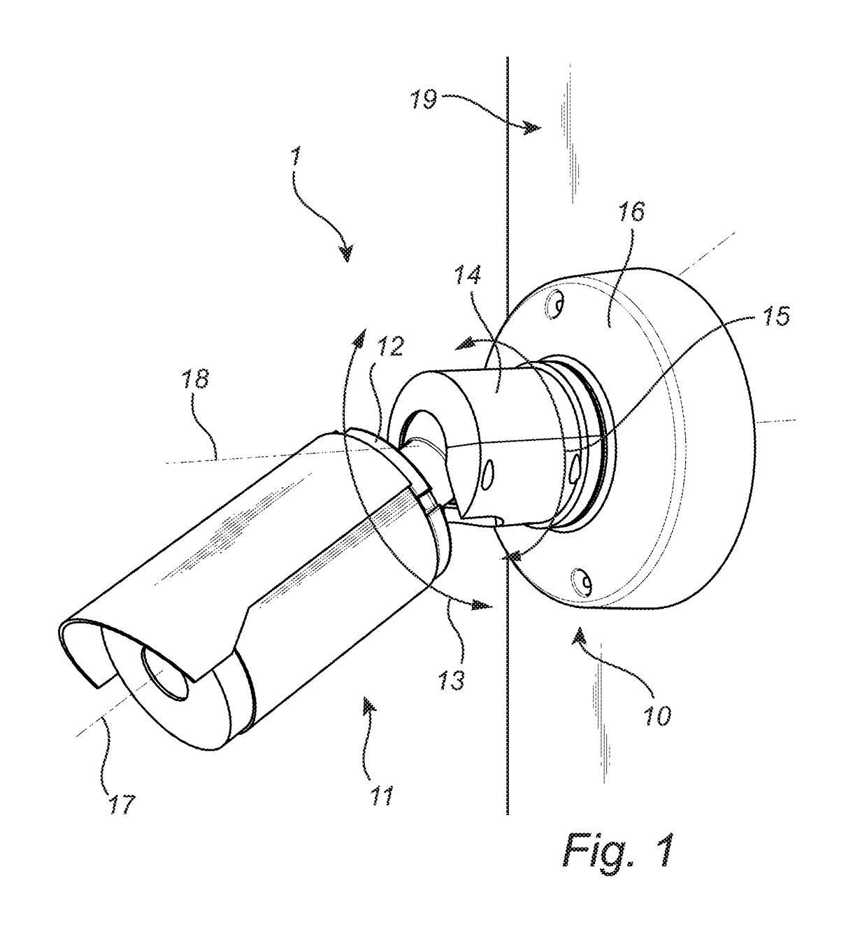
[0041]FIG. 1 illustrates a system 1 comprising an electronic device, in the form of a monitoring camera 11, and a mounting assembly 10. The monitoring camera 11 may comprise a visual or a thermal sensor for capturing visual or thermal images of a monitored scene.

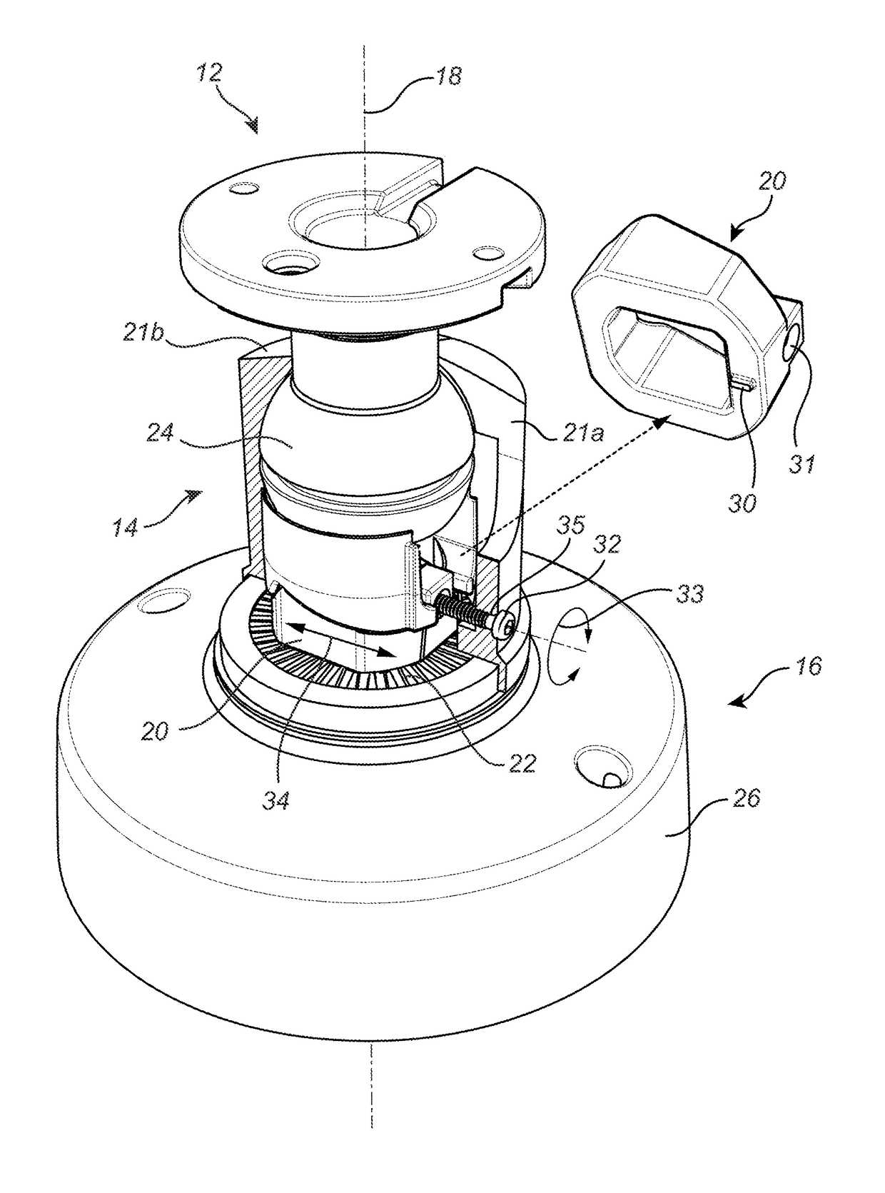
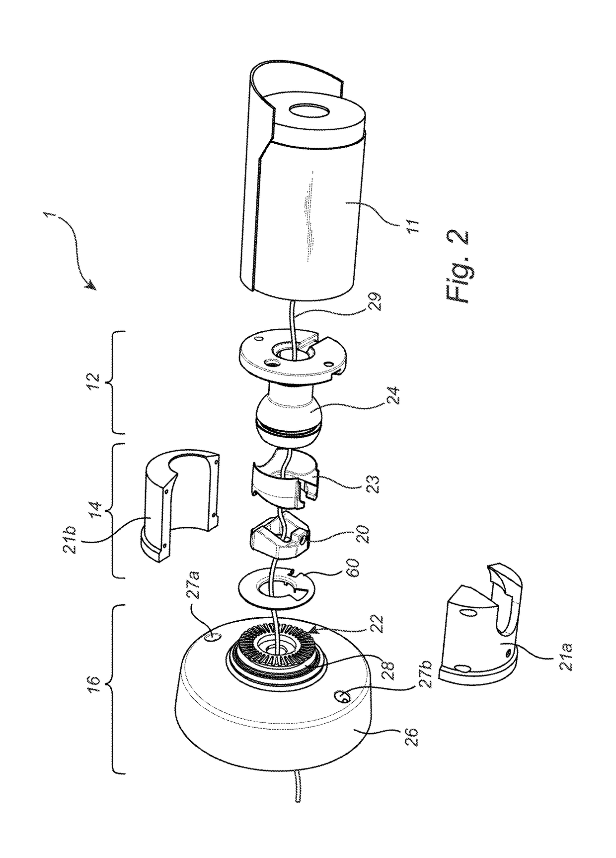
[0042]The mounting assembly 10 comprises a first part in the form of an attachment part 12, a second part in the form of an arm 14, and a third part in the form of a base 16. The monitoring camera 11 is attached to the attachment part 12 by screws or the like. A purpose of the construction of the mounting assembly 10 is to enable mounting of the electronic device, in this case the monitoring camera 11, to a surface 19....


PUM


Abstract

A mounting assembly (10) for an electronic device (11) is disclosed. The mounting assembly (10) comprises an attachment part (12), a base (16), and an arm (14). The attachment part (12) is coupled to the arm (14) and the arm (14) is coupled to the base (16) such that the arm (14) is lockingly rotatable relative the base (16) about a rotational axis (18). The arm (14) comprises a housing and a locking member (20) being provided with a locking protrusion (30). The locking member (20) is coupled to the housing such that the locking protrusion (30) is radially displaceable in relation to the rotational axis (18). The base (16) is provided with a set of radially extending locking grooves (22). The locking protrusion (30) is received by one locking groove (22a) in response to a displacement of the locking member (20), whereby the arm (16) is rotationally locked.

Description

TECHNICAL FIELD[0001]The invention relates to a mounting assembly for an electronic device. Specifically, the invention relates to the arrangement of an attachment part, an arm and a base of the mounting assembly.BACKGROUND OF THE INVENTION[0002]A mounting assembly can be provided for many different types of devices. This patent application relates to a mounting assembly provided for an electronic device. The electronic device is attached to an attachment part of the mounting assembly. The attachment part is in turn coupled to an arm which in turn is coupled to a base. The base may be arranged on, and optionally fastened to, a surface such as a wall, table or a ceiling. The mounting assembly may be arranged for allowing the attachment part, and thus the electronic device attached thereto, to be moved relative the arm by for example a tilt and / or a rotational movement. Additionally, the arm can be arranged to be rotationally movable relative the base.[0003]The mounting assembly may b...

Claims


Application Information

Patent Timeline
Patent Type & Authority Patents(United States)
IPC IPC(8): G03B17/56F16M13/02G08B13/196G03B17/00E05B9/08H04N7/18
CPCG08B13/19632G03B17/561H04N7/18G03B17/00E05B9/08H01R13/639H01R13/6395F16M11/14F16M11/2028F16M13/02F16M2200/024G08B13/19617F16C11/0623
Inventor ROSENKVIST, ALEXANDER
Owner AXIS
Learn More