
Rectal drain appliance

a technology of rectal appliance and auxiliary lumen, which is applied in the direction of instruments, catheters, fluid pressure measurement, etc., can solve the problems of affecting the size of the auxiliary lumen, and achieve the effects of convenient and quick assessment, and convenient us

Active Publication Date: 2018-04-17
CONVATEC TECH INC
View PDF22 Cites 0 Cited by
  • Summary
  • Abstract
  • Description
  • Claims
  • Application Information

AI Technical Summary

Benefits of technology

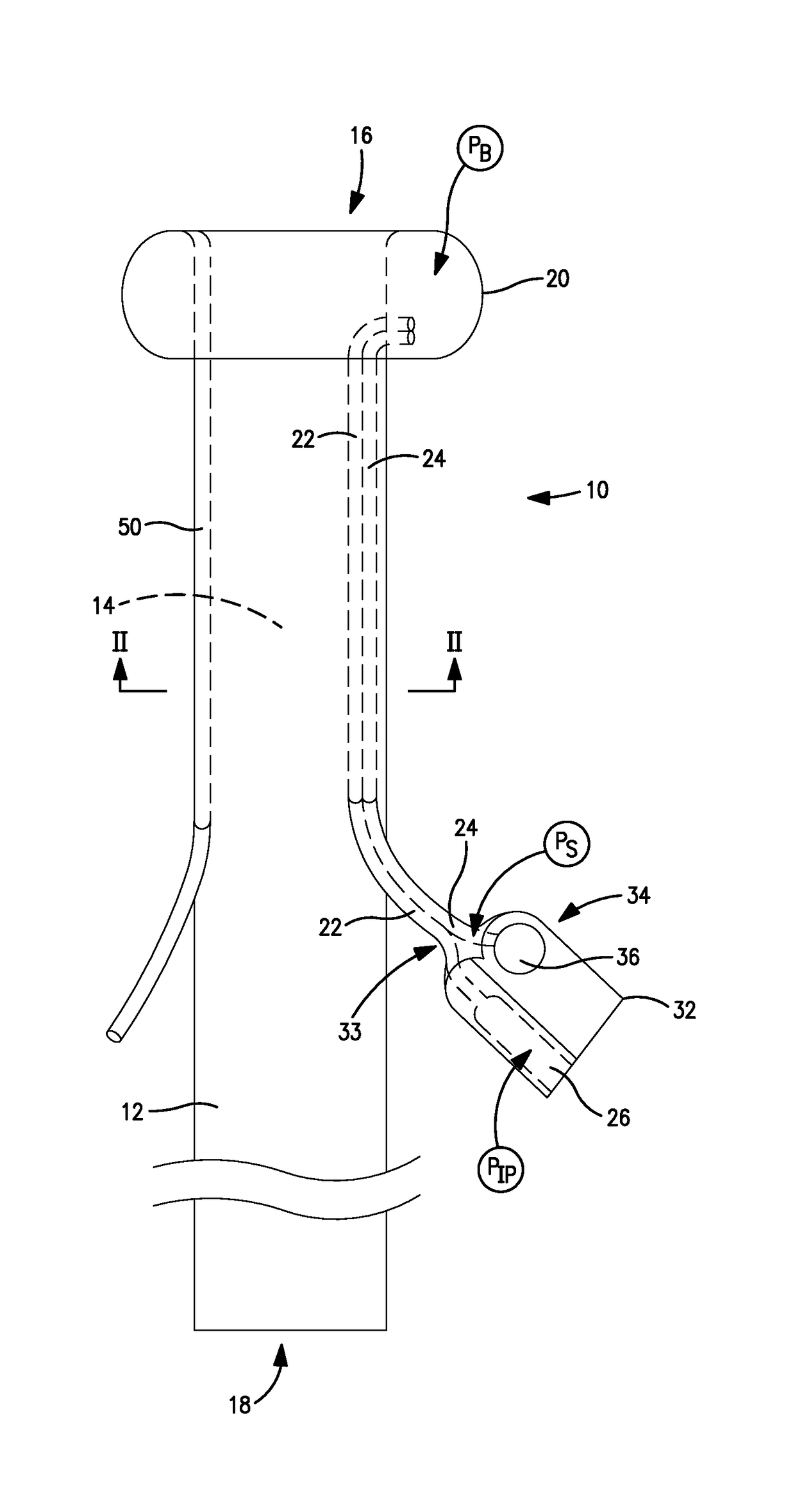
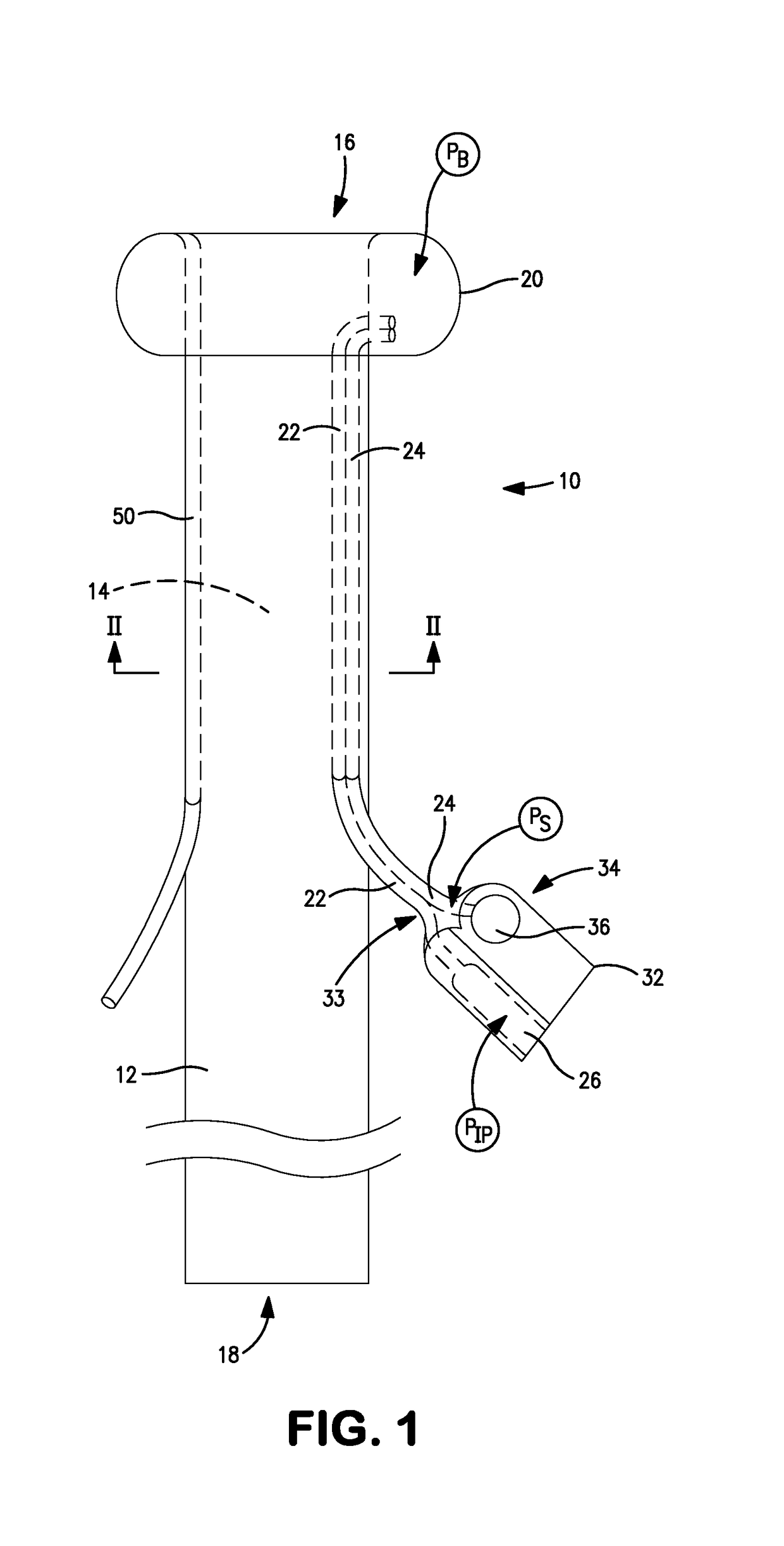
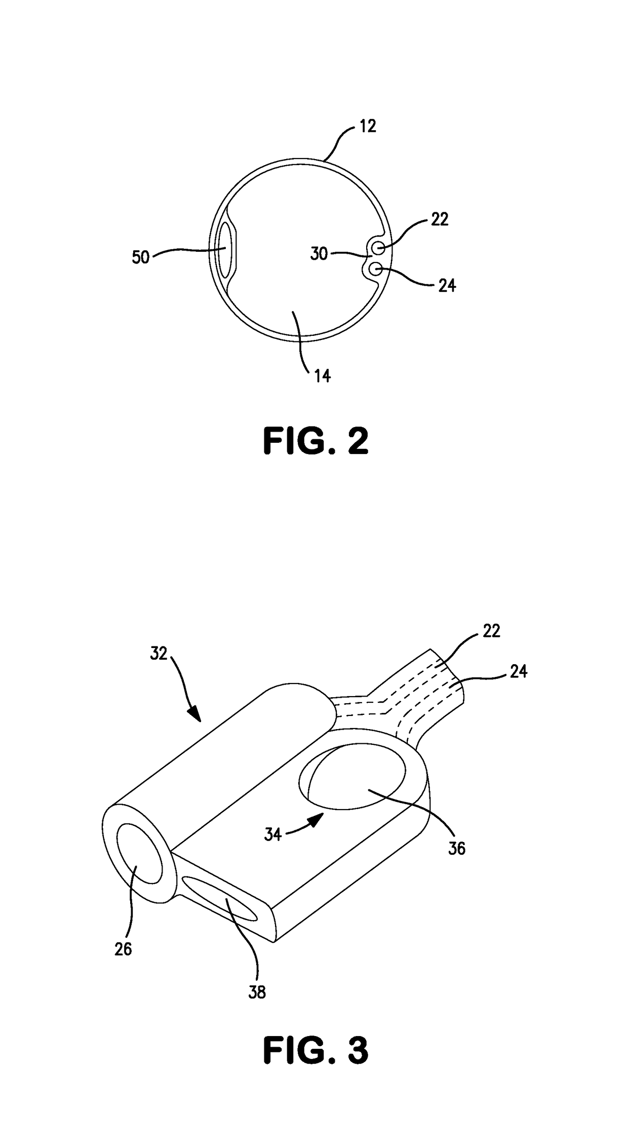
The invention provides a pressure level indicator for a rectal drainage catheter or intestinal drain that can easily and quickly assess the pressure state of the balloon without the need for a variable pressure sensor. The indicator includes a mechanical element that flips between distinct physical states depending on sensed pressure. The mechanical element may be a dome-shaped structure that flips between a non-inverted state and an inverted state. The invention also includes an auxiliary lumen for direct sensing of the internal pressure in the balloon, which is prefilled with inflation fluid to minimize pressure drop. The auxiliary lumen can also be used for various medical purposes such as injecting irrigation fluid or inserting a temperature sensor. When the supply of inflation fluid or medical device is removed, the lumen can collapse to a small size to allow for the desired collapsing property of the tubular element. Overall, the invention provides a more convenient and accurate method for assessing the pressure state of the balloon.

Problems solved by technology

Although not described explicitly in the above published applications, there are also several constraints affecting the size of the auxiliary lumens in the designs illustrated in these applications.

Method used


Image

  • Rectal drain appliance
  • Rectal drain appliance
  • Rectal drain appliance

Examples


second embodiment

[0039]In the embodiment of FIGS. 1-5, the pressure indicator 34 includes a single mechanical element 36 that is configured to represent a single pressure state, such as a predetermined inflation pressure level having been reached (using the first configuration of FIGS. 4(a) and 4(b)). The second embodiment illustrated in FIG. 6 provides two or more mechanical elements 36a, 36b, etc. each configured to indicate a respective different pressure state. For example, first and second mechanical elements 36a, 36b may be provided to show whether the inflation pressure is in a desired inflation range, the lower limit of which is indicated using one mechanical element 36a, and the upper level of which is indicated by the other mechanical element 36b. Both mechanical elements 36a and 36b may be of the first configuration (FIGS. 4(a) and 4(b)). This can enable the clinician to determine whether the inflation pressure is within an optimum operative range, even if the range is relatively narrow. ...

fourth embodiment

[0043]Referring to FIG. 8, a fourth embodiment is illustrated implementing the collapsing auxiliary lumen 50 communicating with the distal end 16, and the dual non-collapsing lumens 22, 24 communicating with the balloon 20. An alternative pressure sensor 70 is provided coupled to the sense lumen 24. The pressure sensor 70 comprises a housing 72 containing a plunger 74 biased by a spring 76. At least a portion of the housing 72 is transparent to permit viewing of the position of the plunger 74, which position is directly indicative of the balloon pressure sensed via the sense lumen 24.


PUM


Abstract

A rectal drainage appliance is disclosed comprising a tubular element having an inflatable balloon at a distal end for anchoring the appliance in the rectum. The appliance includes one or more of: (i) first and second auxiliary lumens communicating with the inflatable balloon to provide independent inflation and pressure monitoring paths coupled to the balloon; (ii) a pressure state indicator defined by a mechanical element configured to flip between first and second states or shapes responsive to sensed pressure; and (iii) a collapsible auxiliary lumen larger than the inflation lumen, and configured to permit admission of irrigation fluid. The pressure state indicator may also be used in intestinal drains.

Description

CROSS-REFERENCE TO RELATED APPLICATIONS[0001]The present application is a national stage application of PCT / US2009 / 042544, filed on May 1, 2009, which claims priority to U.S. Provisional Application No. 61 / 049,578, filed on May 1, 2008.FIELD OF THE INVENTION[0002]The present invention relates to a rectal appliance in the form of a drain tube having an inflatable balloon insertable into the rectum in use. Another aspect of the invention relates to a pressure level indicator for indicating the pressure level within the inflatable balloon(s) of a rectal or intestinal drain.BACKGROUND TO THE INVENTION[0003]U.S. Patent Publication Nos. 2005 / 054996 and 2005 / 137526 describe fecal management appliances in the form of elongate tubular elements. Each tubular element includes an inflatable balloon at the distal end, for anchoring the distal end in an operative position in the wearer's rectum. The tubular element includes a main drain passage, and two small-size auxiliary lumens, similar to eac...

Claims


Application Information

Patent Timeline
Patent Type & Authority Patents(United States)
IPC IPC(8): A61F5/44A61M25/10A61M1/00A61M25/00A61M31/00G01L7/00A61M3/02A61M25/04
CPCA61M3/0295A61M1/0084A61M25/1018A61M25/10187A61M25/10185A61M2210/1067A61M25/04A61M2210/1064A61M25/10184A61M1/85
Inventor GREGORY, CHRISTOPHER
Owner CONVATEC TECH INC
Learn More