Spark containment cap

a technology of containment cap and spark, applied in the field of caps, can solve problems such as bubbles or other defects, and achieve the effects of convenient installation, convenient application, and convenient application

Active Publication Date: 2018-04-24
AIRBUS OPERATIONS LTD
View PDF13 Cites 11 Cited by
  • Summary
  • Abstract
  • Description
  • Claims
  • Application Information

AI Technical Summary

Benefits of technology

[0008]This arrangement enables the aperture to remain open while the bead of sealing material cures, and be closed after it has at least partially cured. When the aperture is open the cavity is in fluid communication with the external atmosphere, thus ensuring that there is no, or only a minimal, pressure difference between the gas / air within the cavity and the gas / air outside the cavity. This is important because such a pressure difference may cause the gas / air to be forced into / out of the cavity so that it forms bubbles or other defects in the uncured annular bead of sealing material.
[0022]As for the first and second aspects, by sealing the aperture after the bead of sealing material has at least partially cured the air cavity remains in fluid communication with the external atmosphere, thus avoiding a pressure differential therebetween.

Problems solved by technology

This is important because such a pressure difference may cause the gas / air to be forced into / out of the cavity so that it forms bubbles or other defects in the uncured annular bead of sealing material.

Method used


Image

  • Spark containment cap
  • Spark containment cap
  • Spark containment cap

Examples


Embodiment Construction

)

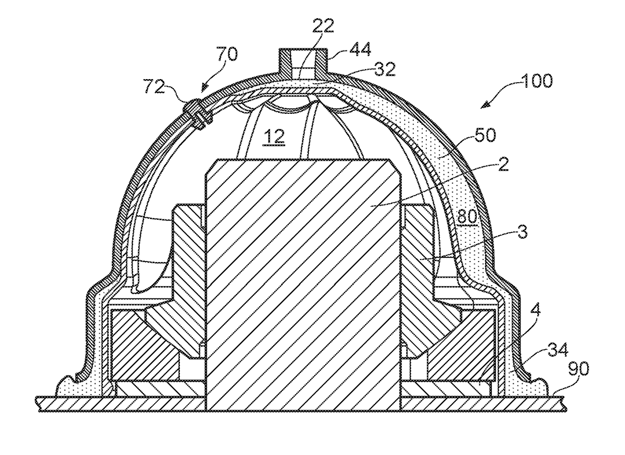
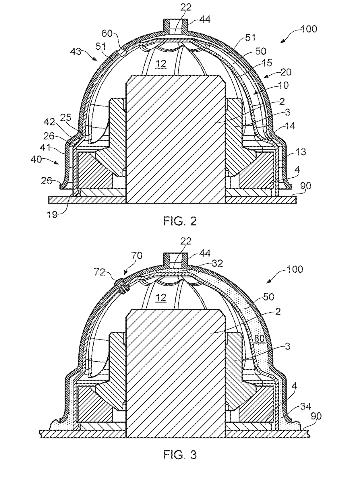
[0032]FIGS. 2 to 4 show an injectable nut cap 100 according to a first embodiment of the present invention. The nut cap includes an inner cap member 10 and an outer cap member 20. The inner and outer cap members 10, 20 are injection moulded from a thermoplastic material such as glass-filled polyetherimide (PEI). A suitable glass-filled PEI is Ultem™ 2400, which includes 40% glass fibres by volume. The inner and outer cap members may alternatively be made by moulding, by an additive manufacturing process, or by any other suitable process.

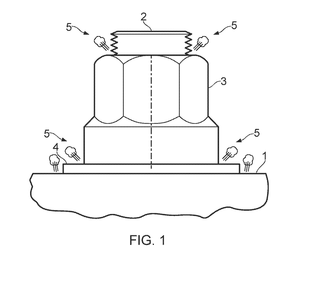
[0033]The inner cap member 10 is a generally thin-walled dome-shaped member, with a correspondingly dome-shaped inner air cavity 12 which encloses the tail end of a fastener protruding from a structural element, which in this embodiment is a composite aircraft structural component 90, but may be a hybrid composite-metallic component. The fastener comprises a bolt 2 in threaded engagement with a nut 3, or collar, which engages the structural componen...


PUM


Abstract

A spark containment cap is disclosed for enclosing an end of a fastener protruding from a structure. The cap includes a cap body having an annular base terminating at a rim which surrounds an opening into an air cavity arranged to enclose the fastener end and having an aperture in fluid communication with the cavity. An annular bead of uncured sealing material is provided around the opening into the cavity, the bead of sealing material being curable to provide a seal between the cap body and the structure to seal a volume of gas within the cavity. A closure member has a closed configuration in which it seals the aperture, and an open configuration in which it does not seal the aperture.

Description

RELATED APPLICATIONS[0001]The present application claims priority from Great Britain Application Number 1422333.3, filed Dec. 16, 2014, the disclosure of which is hereby incorporated by reference herein in its entirety.FIELD OF THE INVENTION[0002]The present invention relates to a cap and a kit of parts for forming a sealed cavity around one end of a fastener, a method of installing such a cap, and a joint comprising such a cap.BACKGROUND OF THE INVENTION[0003]Large passenger aircraft are typically struck by lightning once or twice a year, each lightning bolt striking with up to 200,000 amps of electrical current that seeks the path of least electrical resistance. Many modern passenger aircraft have exterior surfaces made from composite materials which have a very high electrical resistance. There is therefore a high probability of lightening attachment at any of the many metallic fasteners in the exterior surface, which have a much lower electrical resistance. In the wing, some of ...

Claims


Application Information

Patent Timeline
Patent Type & Authority Patents(United States)
IPC IPC(8): F16B37/14B64D45/02F16B33/00
CPCF16B37/14B64D45/02F16B33/004
Inventor DOBBIN, RICHARDHUMPHRYS, BEN
Owner AIRBUS OPERATIONS LTD
Why Eureka
Try Eureka