3D display system
a display system and display technology, applied in the field of television, can solve problems such as the emission of reflected light from the display system, and achieve the effect of thin form factor
- Summary
- Abstract
- Description
- Claims
- Application Information
AI Technical Summary
Benefits of technology
Problems solved by technology
Method used
Image
Examples
example 1
orientation Due to Clear Spot Movement
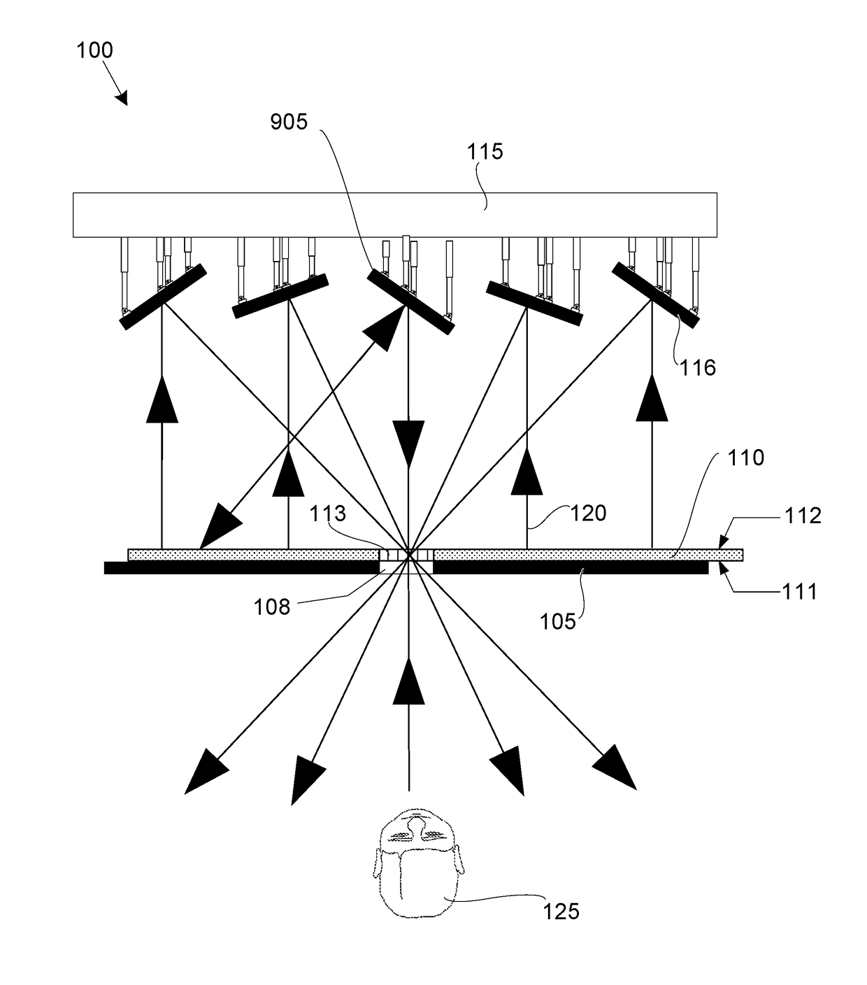
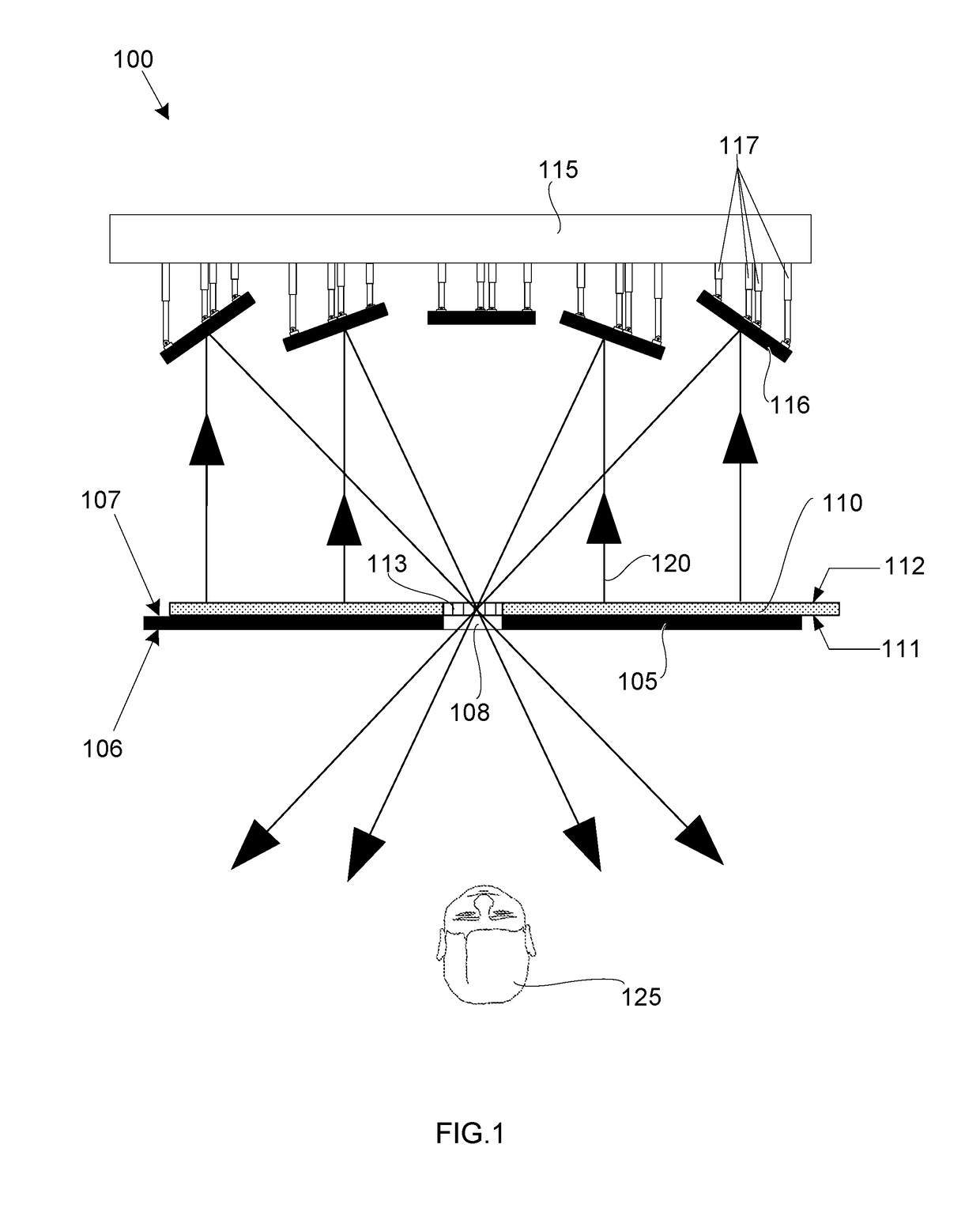
[0052]An exemplary embodiment is illustrated in FIG. 6A and FIG. 6B, showing an array of mirrors (405) in the electromechanical system (115). The array of mirrors (405) is configured for reorientation. FIG. 6A and FIG. 6B are respectively top views of a display system at two different times, T1 in FIG. 6A and T2 in FIG. 6B. These figures in comparison show the same 6 mirrors in the array of mirrors (405), from the same perspective, in a first state at time T1 in FIG. 6A and in a second subsequent state at time T2 in FIG. 6B. The mirrors are shown changing their orientations in conjunction with a change in the location of the clear spot (113) in a transparent organic light-emitting diode display (605) overlaying a transparent spot (108) in the parallax barrier (105), thus enabling light (120) reflected from the array of mirrors (405) to exit the display system (100) towards the viewer (125) at both times.
example 2
orientation Due to Display System Component Separation
[0053]An exemplary embodiment is illustrated in FIG. 7A and FIG. 7B, which show side by side top views of a display system at two different times, T1 in FIG. 7A and T2 in FIG. 7B. The combined figures show mirrors in the array of mirrors (405) changing their orientations in conjunction with the transparent organic light-emitting diode display (605) and the parallax barrier (105) being moved further away from the mirror array (i.e. from first position 705 at T1 to second position 710 at T2). The reorientation of the mirrors enables light (120) from the transparent OLED display (605) to exit the display system at both times.
example 3
nt OLED Display Image Source Layer and LCD Parallax Barrier
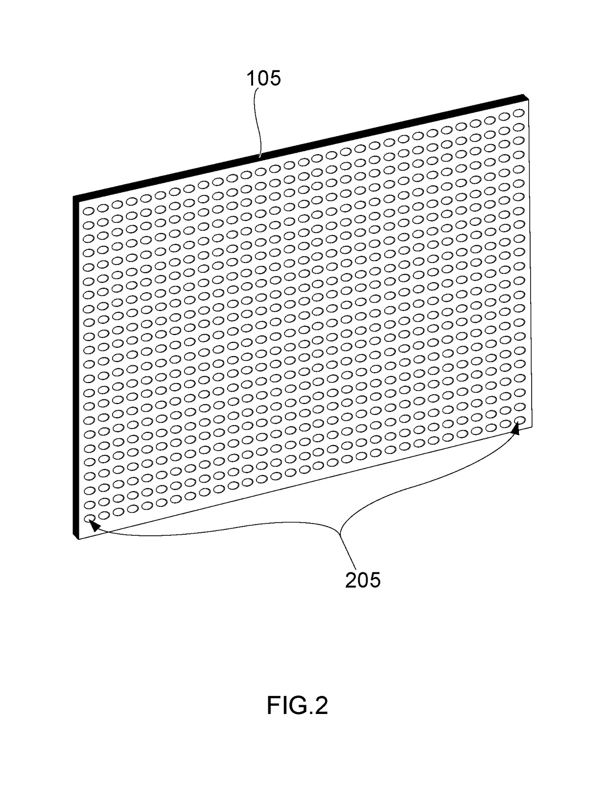
[0054]An exemplary embodiment is illustrated in FIG. 8, which shows a top view of a display system where the parallax barrier is a liquid crystal display (805) (LCD), the image source layer is a transparent organic light-emitting diode display (605) (transparent OLED display) located immediately behind the LCD from the perspective of a viewer (125), and the electromechanical system (115) is located behind the LCD from the perspective of a viewer (125). Use of an LCD as the parallax barrier (105) enables a dynamic display in which the transparent spots in the array of transparent spots (205) on the parallax barrier (105) can be manipulated to change location. The mirrors in the array of mirrors (405) reflect the light emitted away from the LCD (i.e. the parallax barrier) by the transparent OLED display. The light (120) reflected from the array of mirrors (405) shines through the clear spot (113) in the transparent organic lig...
PUM
 Abstract
Description
Claims
Application Information
 - R&D
- Intellectual Property
- Life Sciences
- Materials
- Tech Scout
- Unparalleled Data Quality
- Higher Quality Content
- 60% Fewer Hallucinations
Browse by: Latest US Patents, China's latest patents, Technical Efficacy Thesaurus, Application Domain, Technology Topic, Popular Technical Reports.
© 2025 PatSnap. All rights reserved.Legal|Privacy policy|Modern Slavery Act Transparency Statement|Sitemap|About US| Contact US: help@patsnap.com


