
Beverage container for injecting beverage through bottom thereof

a beverage container and beverage technology, applied in the field of beverage containers, can solve the problems of large amount of foam, degrading the taste of draft beers, and having to remove foam, and achieve the effects of convenient use, maximum maintenance, and convenient manufacturing of beverage containers

Active Publication Date: 2018-05-01
NPC CO LTD
View PDF16 Cites 3 Cited by
  • Summary
  • Abstract
  • Description
  • Claims
  • Application Information

AI Technical Summary

Benefits of technology

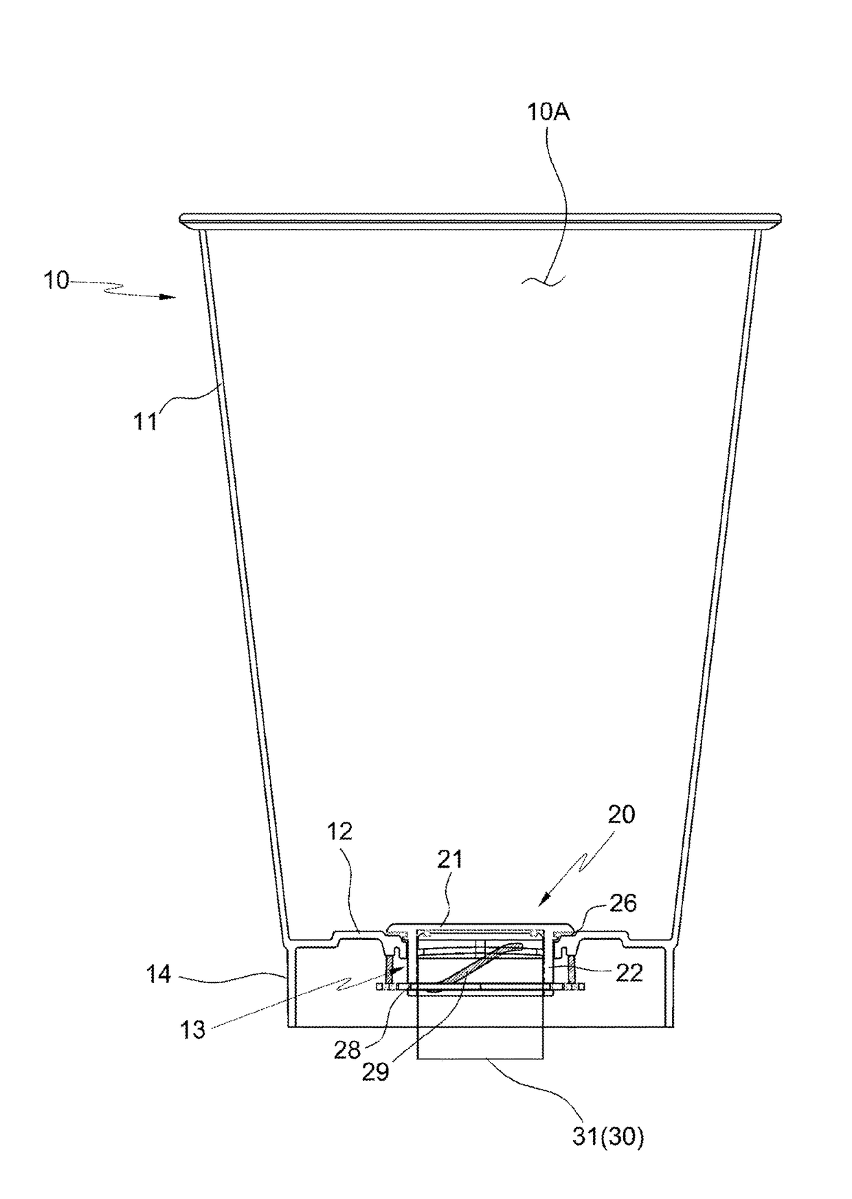
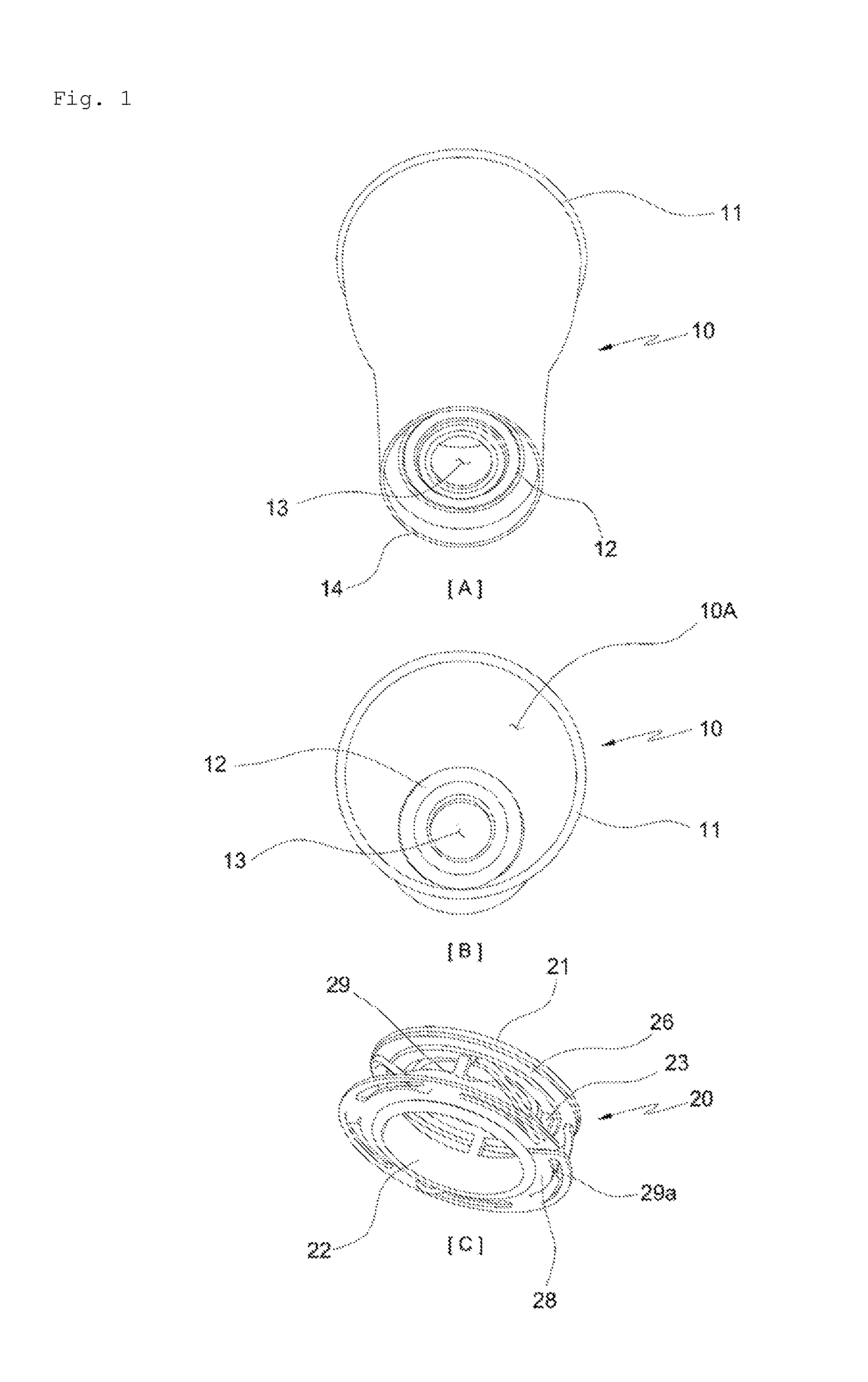
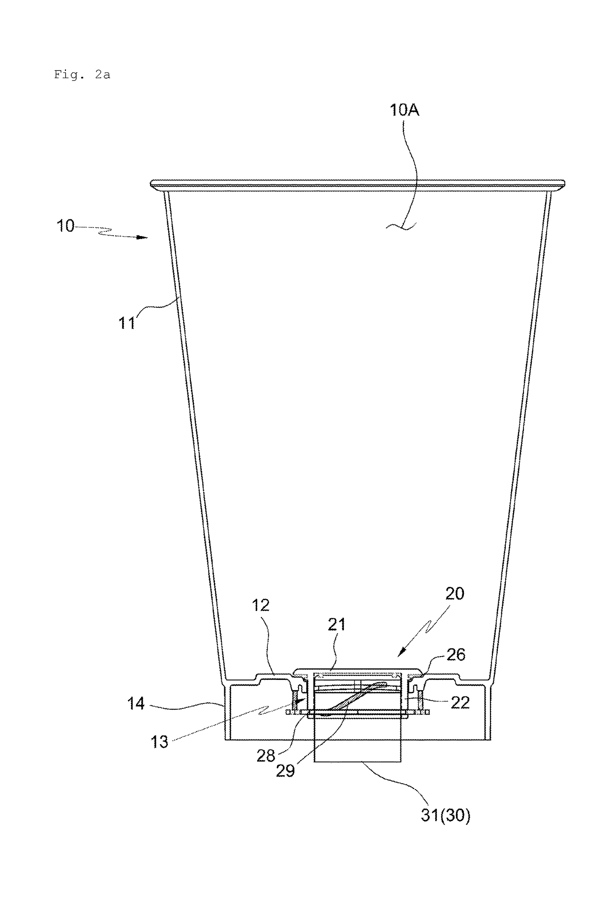
[0029]A beverage container for injecting beverages through the bottom thereof according to the present invention may properly maintain the amount of foams produced when pouring beverages such as beers and the like since beverage injection is performed from the bottom by coupling the nozzle of the beverage supplying apparatus to the inlet formed in the bottom, and may provide best quality beverages by maximally maintaining the original taste of the beverages not allowing the beverages to be in contact with air and oxidized during pouring of the beverages.
[0030]Especially, the beverage container for injecting beverages through the bottom thereof according to the present invention is: convenient in use by adopting a holder and a locking member capable of automatically performing the opening and closing operation of the holder which is coupled to the inlet without requiring any separate operation when the main body of the beverage container is engaged and disengaged with the nozzle of the beverage supplying apparatus; harmless since the beverages are not exposed to and not in contacted with other components harmful to human by not requiring any separate elements (for example, magnets) and the like for the opening and closing operation of the holder; useful in that this new way of beverage injection can be utilized in marketing for a beer specialty store and the like; and very useful for popularization of the beverage container for injecting beverages in a unique way since the manufacturing of such beverage container is easy and it can be supplied with low price.
[0031]In addition, the beverage container for injecting beverages through the bottom thereof according to the present invention is capable of stably preventing the beverages from leaking out through the inlet in the bottom even when the beverage container is used for a long time by completely closing the inlet while enhancing the productivity of the manufacturing and assembling thereof; and more particularly,
[0032]the beverage container for injecting beverages through the bottom thereof according to the present invention is advantageous for a long time usage since the failure and damage of the holder and the like can be minimized because the closing state of the inlet is maintained through the locking member having a structure wherein the holder is simplified.
[0033]Further, the beverage container for injecting beverages through the bottom thereof according to the present invention is capable of fundamentally blocking the leaking out of the beverage inside the main body by providing a packing member in the upper wall body of the holder since the gap between the holder and the bottom is sealed by the packing member under the state wherein the inlet is closed by the holder.
[0034]In addition, the beverage container for injecting beverages through the bottom thereof according to the present invention is easy to manufacture and may reduce the manufacturing cost since any separate element or structure and the like is not necessary in order to add an elastic member such as a spring and the like for automatic returning of the holder since the elastic arm is formed by cutting a portion of the body of the locking member and bending upwardly.

Problems solved by technology

Beer has a relatively lower alcohol concentration among the liquors and thus anybody can simply enjoy without an imposition; however, unlike other beverages, a draft beer is being supplied through a beverage supplying apparatus and poured into the beer cup through the opening in the upper portion thereof causing a large amount of foams due to the injection pressure, so there has been inconveniences in that the foams have to be removed every time after the beverage is injected into a container such as a beer cup and the like.
Thus, since draft beers are mostly being supplied from the upper side when being supplied to a beverage container using a draft beer supplying apparatus of the prior art, a large amount of foams are produced when the temperature is inappropriate causing wetting of clothes due to spillover, or undesirable in the aspects of sanitation; and moreover, there is a problem in that the taste of the draft beers are being degraded due to the excessive foams.
Furthermore, a conventional beer cup has a problem in that the taste of the beer is degraded due to oxidation thereof due to contact of the beer with air when pouring the beer, and such phenomenon becomes more significant when drinking a draft beer.
The amount of foams of draft beers can be appropriately maintained when the draft beers are being supplied after forming a hole in the bottom surface of the beverage container for solving the above described problems; however, there is a problem in that this method cannot be adopted since no adequate method is available for sealing the hole in the bottom of the beverage container after the draft beer has been injected via the hole.
However, since a magnetic force blocking unit having magnetic force and made of metallic material is used in the prior art, beverages may easily be in contact with the magnetic force blocking unit; and such contact may have a high risk of rust and the like which may spoil the beverages when the beverage cup is being used for a long time; thus, there is a problem in that the effectiveness is being degraded as a beverage container directly used for drinking by a human in the aspects of sanitary control and harmlessness to human body.
Especially, the adoption of the foresaid prior art requires a sealing technique for preventing the above mentioned magnetic force blocking unit from contacting with the beverages; such manufacturing method is not only unreasonable in the aspects of the manufacturability of the beverage cup, but also the manufacturing cost thereof will be increased; so there is a limitation in popularization of such beverage cup as a low cost consumable product.

Method used


Image

  • Beverage container for injecting beverage through bottom thereof
  • Beverage container for injecting beverage through bottom thereof
  • Beverage container for injecting beverage through bottom thereof

Examples


Embodiment Construction

[0039]This invention may be variously modified and embodied in many different forms, and embodiments (or aspects) are to be specifically described herein. However, this invention should not be construed as limited to specific disclosure forms, and the spirit and scope of the invention should be understood as incorporating various modifications, equivalents and substitutions.

[0040]Wherever possible, the same reference numerals in the drawings, in particular, the reference numerals in which a two-digit number and one-digit number are the same or a two-digit number, one-digit number and letters of the alphabet are the same, will be used throughout the drawings and the description to refer to the same or like members. Unless otherwise stated, the members designated by respective reference numerals in the drawings are regarded as members based on such standards.

[0041]In the drawings, the sizes or thicknesses of elements are expressed excessively large (or thick) or small (or thin) or in ...


PUM


Abstract

A beverage container has a body having an inlet which is formed so as to penetrate the bottom of a receiving unit. A holder is coupled to the inlet to open and close the inlet upon ascending or descending with a nozzle of a beverage supply device being inserted into the holder. A locking member is coupled to the ascending / descending wall of the holder to allow the holder to close the inlet. The locking member has a plurality of elastic arms for elastically supporting the holder.

Description

[0001]This application is the national phase entry of international patent application no. PCT / KR2014 / 010904 filed Nov. 13, 2014 and claims the benefit of Korean patent application No. 10-2014-0085888, filed Jul. 9, 2014, the disclosures of which are incorporated herein by reference in their entirety.TECHNICAL FIELD[0002]The present invention relates to a beverage container for injecting beverages through the bottom thereof, and more particularly to a beverage container for injecting the beverages through the bottom thereof, which is capable of maximally maintaining the taste of a beverage by minimizing contact with air; and at the same time, excessive foam formation resulting from a head drop when pouring the beverages can be prevented by filling the beverage container with the beverages from the lower part of a receiving unit of the beverage container through an inlet disposed at the bottom of the beverage container when drinking liquid beverages such as beers.BACKGROUND ART[0003]...

Claims


Application Information

Patent Timeline
Patent Type & Authority Patents(United States)
IPC IPC(8): B67D7/02B65D47/20B65D47/06B65D53/02A47G19/22B67D1/12B65D55/02B65D85/72B67D1/08B67D7/42
CPCB67D7/0288A47G19/2205B65D47/06B65D47/20B65D53/02B65D85/72B67D1/0894B67D1/1272B65D55/02B67D2210/00065B67D7/42
Inventor PARK, SUK JOONGLEE, SI HAENG
Owner NPC CO LTD
Learn More