
Modular foundation system and method

a foundation system and module technology, applied in the field of modular foundation systems, can solve the problems of weakening the overall foundation, onsite poured foundation is not cost-effective or practical, and the access can be difficult, so as to achieve cost-effectiveness, incomplexity, and durable

Active Publication Date: 2018-05-01
PRE CON PROD
View PDF42 Cites 2 Cited by
  • Summary
  • Abstract
  • Description
  • Claims
  • Application Information

AI Technical Summary

Benefits of technology

[0008]The present invention seeks to provide modular foundation systems and methods for securing and stabilizing structures and apparatuses with an improved and customizable approach that is durable, cost-effective, and incomplex.

Problems solved by technology

However, many of these structures and apparatuses are often needed in remote locations where access can be difficult and / or in locations where installation of a traditional, onsite poured foundation is not cost-effective or practical.
This results in a foundation that can readily bend at various hinge points should the post-tensioning mechanism fail, which can weaken the overall foundation.
Moreover, various existing foundation systems comprise overall shapes that may not match the base shape of the structure and / or apparatus the system is supposed to stabilize.
This can be inefficient or less efficient than providing a foundation system with an overall shape that generally matches the base shape of what is to be stabilized.
Additionally, it can be problematic as the bolts and bolt holes used to anchor the structure or apparatus to the foundation system may not take site variations into account and thus may not be perfectly aligned during onsite assembly.

Method used


Image

  • Modular foundation system and method
  • Modular foundation system and method
  • Modular foundation system and method

Examples


Embodiment Construction

[0030]The present invention is described herein with reference to certain embodiments, but it is understood that the invention can be embodied in many different forms and should not be construed as limited to the embodiments set forth herein.

[0031]Although the terms first, second, etc. may be used herein to describe various elements, components, regions, and / or sections, these elements, components, regions, and / or sections should not be limited by these terms. These terms are only used to distinguish one element, component, region, or section from another element, component, region, or section. Thus, a first element, component, region, or section discussed below could be termed a second element, component, regions, or section without departing from the teachings of the present invention.

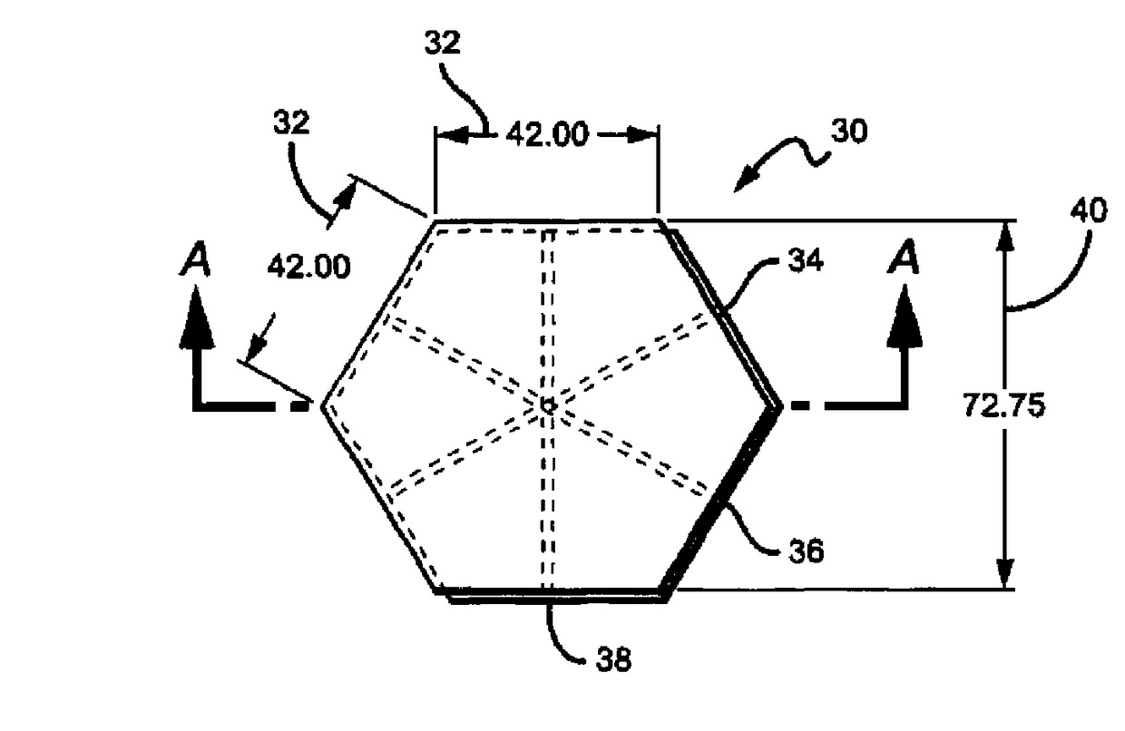
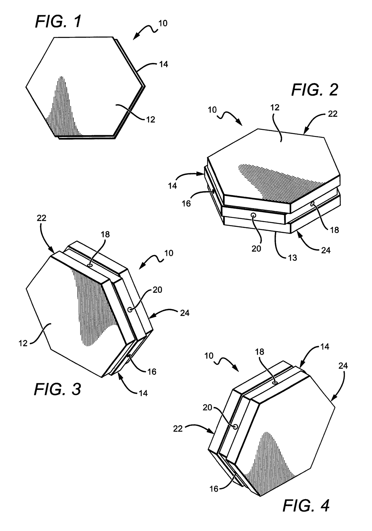
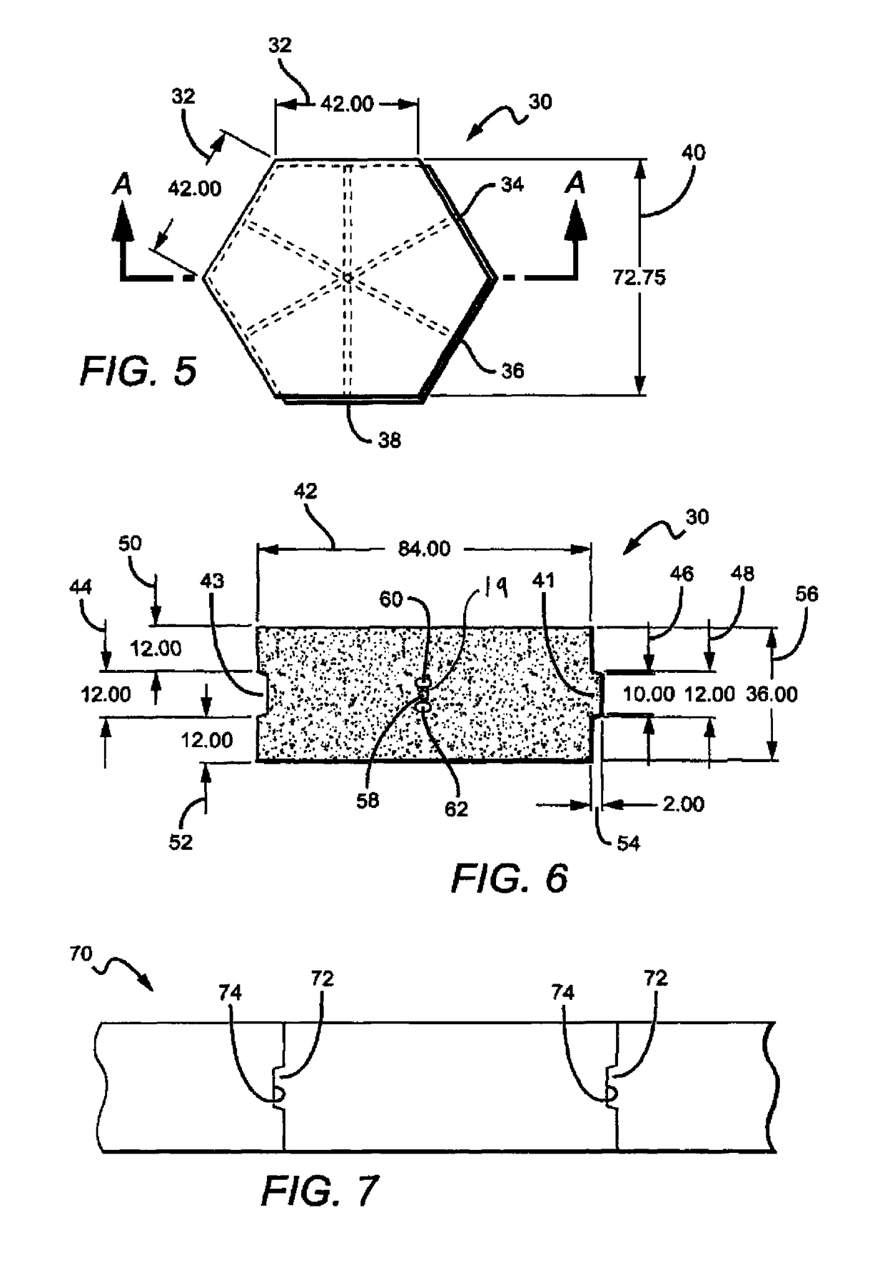
[0032]FIGS. 1-4 show one embodiment of a modular block 10 constructed in accordance with the present invention, having: a first surface 12; a second surface 13 opposite the first surface 12; a middle...


PUM


Abstract

The present invention is directed to a customizable, modular foundation system using blocks and post-tensioning for improved structural integrity of the foundation. In some embodiments, the improved foundation system is provided by post-tensioning a plurality of blocks together such that cables or bars used for tensioning run in different directions than any of the joint lines between adjacent blocks. In this way, there are no bendable joints between adjacent blocks. Moreover, in some embodiments the blocks are hexagonal, such that each block has six sides and post-tensioning cables can run in at least three different directions. Structures or apparatuses may be secured to the foundation comprised of multiple blocks, with the foundation being rigid, customizable, and both assembled and usable in any desired location.

Description

[0001]This application claims the benefit of U.S. Provisional Application No. 61 / 243,026 to Zarraonandia, which was filed on 16 Sep. 2009.BACKGROUND OF THE INVENTION[0002]Field of the Invention[0003]This invention relates to foundation systems and more particularly to modular foundation systems for supporting structures such as towers, shelters, antennas, and the like as well as apparatuses such as generators, fuel tanks, and the like.[0004]Description of the Related Art[0005]Structures such as towers, antennas, and shelters and apparatuses such as generators and fuel tanks often require foundations to ensure proper support and stability. Numerous foundation systems have been developed over the years to attempt to stabilize such structures and apparatuses. However, many of these structures and apparatuses are often needed in remote locations where access can be difficult and / or in locations where installation of a traditional, onsite poured foundation is not cost-effective or practi...

Claims


Application Information

Patent Timeline
Patent Type & Authority Patents(United States)
IPC IPC(8): E02D27/01E02D29/02E02D27/32E04C1/39
CPCE02D27/01E02D27/32E04C1/39E02D29/025E02D27/016
Inventor ZARRAONANDIA, DAVID
Owner PRE CON PROD
Learn More