Flying lane management systems and methods for unmanned aerial vehicles

a technology of flying lane management and unmanned aerial vehicles, applied in vehicle position/course/altitude control, process and machine control, instruments, etc., can solve the problems of collisions, impracticality of using the air traffic control network for uavs,

Active Publication Date: 2018-05-01
METAL RAPTOR LLC
View PDF35 Cites 16 Cited by
  • Summary
  • Abstract
  • Description
  • Claims
  • Application Information

AI Technical Summary

Benefits of technology

[0009]In another exemplary embodiment, an air traffic control system communicatively coupled to one or more Unmanned Aerial Vehicles (UAVs) via one or more wireless networks adapted to perform flying lane management includes a network interface and one or more processors communicatively coupled to one another; and memory storing instructions that, when executed, cause the one or more processors to: initiate communication to the one or more UAVs at a preflight stage for each, wherein the communication is via one or more cell towers associated with the one or more wireless networks, wherein the plurality of UAVs each include hardware and antennas adapted to communicate to the plurality of cell towers; determine a flying lane for the one or more UAVs based on a destination, current air traffic in a region under management of the air traffic control system, and based on detected obstructions in the region; and provide the flying lane to the one or more UAVs are an approval to takeoff and fly along the flying lane. The instructions, when executed, can further cause the one or more processors to: continue the communication during flight on the flying lane and receiving data from the one or more UAVs, wherein the data include feedback during the flight; and utilize the feedback to update the flying lane, to update other flying lanes, and to manage air traffic in the region.
[0010]During the flight, the feedback includes speed, altitude, and heading, and the feedback can further include one or more of temperature, humidity, wind, and detected obstructions. The instructions, when executed, can further cause the one or more processors to: provide updates to the flying lane based on the feedback and based on feedback from other devices. The instructions, when executed, can further cause the one or more processors to: based on the feedback, determine the one or more UAVs at ready to descend or fly to the destination and providing authorization to the one or more UAVs for a descent. The instructions, when executed, can further cause the one or more processors to: based on the feedback, detect a new obstruction; and one of update the flying lane based on adjustments made by the one or more UAVs due to the new obstruction and provide an updated flying lane due to the new obstruction. The adjustments and / or the updated flying lane can include a buffer distance from the new obstruction. The new obstruction can be detected by the one or more UAVs based on hardware thereon and communicated to the air traffic control system. The air traffic control system can be adapted to operate autonomously.

Problems solved by technology

However, it is impractical to use the existing air traffic control network for UAVs because of the sheer quantity of UAVs.
As the number of applications increase and the number of UAVs concurrently in flight also increase, there are various issues that have to be addressed relative to air traffic control.
However, once UAVs begin widespread delivery applications, collisions will be a major problem due to the potential damage to deliveries as well as threats to people and property on the ground.

Method used


Image

  • Flying lane management systems and methods for unmanned aerial vehicles
  • Flying lane management systems and methods for unmanned aerial vehicles
  • Flying lane management systems and methods for unmanned aerial vehicles

Examples


Embodiment Construction

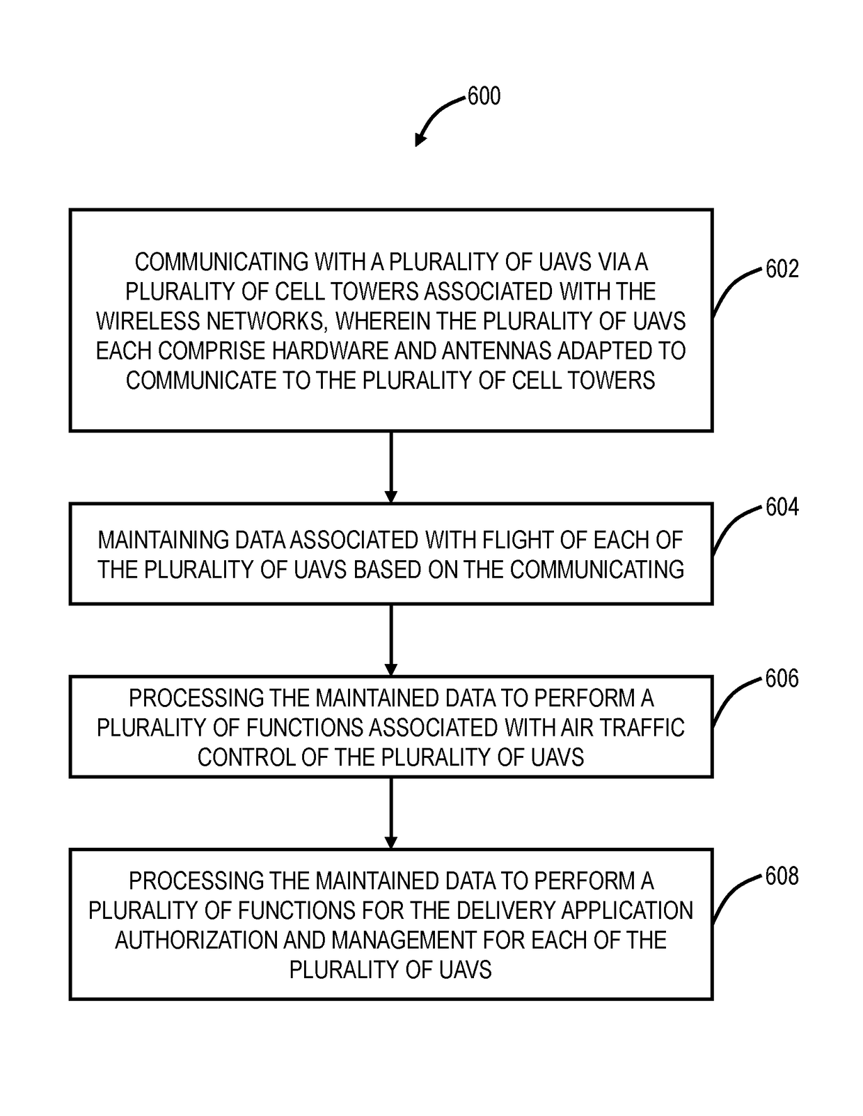
[0036]Again, in various exemplary embodiments, flying lane management systems and methods are described for UAVs such as through an air traffic control system that uses one or more wireless networks. As described herein, a flying lane for a UAV represents its path from takeoff to landing at a certain time. The objective of flying lane management is to prevent collisions, congestion, etc. with UAVs in flight. A flying lane can be modeled as a vector which includes coordinates and altitude (i.e., x, y, and z coordinates) at a specified time. The flying lane also can include speed and heading such that the future location can be determined. The flying lane management systems utilize one or more wireless networks to manage UAVs in various applications.

[0037]Note, flying lanes for UAVs have significant differences from conventional air traffic control flying lanes for aircraft (i.e., commercial airliners). First, there will be orders of magnitude more UAVs in flight than aircraft. This c...


PUM


Abstract

A flying lane management method implemented in an air traffic control system communicatively coupled to one or more Unmanned Aerial Vehicles (UAVs) via one or more wireless networks includes initiating communication to the one or more UAVs at a preflight stage for each, wherein the communication is via one or more cell towers associated with the one or more wireless networks, wherein the plurality of UAVs each comprise hardware and antennas adapted to communicate to the plurality of cell towers; determining a flying lane for the one or more UAVs based on a destination, current air traffic in a region under management of the air traffic control system, and based on detected obstructions in the region; and providing the flying lane to the one or more UAVs are an approval to takeoff and fly along the flying lane.

Description

CROSS-REFERENCE TO RELATED APPLICATION(S)[0001]The present patent / application is continuation-in-part of, and the content of each is incorporated by reference herein[0002]Filing DateSer. No.TitleJun. 27, 201615 / 193,488AIR TRAFFIC CONTROL OFUNMANNED AERIAL VEHICLES FORDELIVERY APPLICATIONSJun. 17, 201615 / 185,598AIR TRAFFIC CONTROL OFUNMANNED AERIAL VEHICLESCONCURRENTLY USING APLURALITY OF WIRELESSNETWORKSJun. 10, 201615 / 179,188AIR TRAFFIC CONTROL OFUNMANNED AERIAL VEHICLES VIAWIRELESS NETWORKSFIELD OF THE DISCLOSURE[0003]The present disclosure relates generally to systems and methods to control Unmanned Aerial Vehicles (UAVs or “drones”). More particularly, the present disclosure relates to flying lane management systems and methods for UAVs such as through an air traffic control system that uses one or more wireless networks.BACKGROUND OF THE DISCLOSURE[0004]Use of Unmanned Aerial Vehicles (UAVs or “drones”) is proliferating. UAVs are used for a variety of applications such as searc...

Claims


Application Information

Patent Timeline
Patent Type & Authority Patents(United States)
IPC IPC(8): G08G5/00G08G5/02G08G5/04B64C39/02G05D1/00B64D47/08
CPCG08G5/0043B64C39/024B64D47/08G05D1/0011G08G5/045G08G5/0034G08G5/0039G08G5/0091G08G5/025G05D1/0088G08G5/0013G08G5/0026G08G5/0069G08G5/0082B64U2201/00
Inventor PRIEST, LEE
Owner METAL RAPTOR LLC
Why Eureka
Try Eureka