Free Piston Engine Power Plant

a technology of free piston engine and power plant, which is applied in the direction of engines without rotary main shafts, machines/engines, mechanical equipment, etc., can solve the problems of unsatisfactory pulsating flow from the engin

Active Publication Date: 2019-02-21
UNIVERSITY OF DURHAM
View PDF4 Cites 6 Cited by
  • Summary
  • Abstract
  • Description
  • Claims
  • Application Information

AI Technical Summary

Benefits of technology

[0047]Optionally, a second steam path injector and a second steam path valve may be provided on the second steam path to control the amount of steam supplied to the second path. Advantageously, this permits the use of steam for load control of the power plant, while at the same time utilising excess energy for other purposes, and allows the power plant to adapt its operation according to any given operational requirements.

Problems solved by technology

A challenge in free-piston engines is the control of the piston motion, since the piston assembly is not restrained in its motion by a crank mechanism but will move freely under the influence of the different forces acting on it at any given time.
In free-piston gas generators, a further challenge is the matching of the (reciprocating) free-piston combustion engine with the (rotodynamic) power turbine.
This is because the pulsating flow from the engine is not ideal for a turbine, which provides best efficiency under steady flow conditions.

Method used


Image

  • Free Piston Engine Power Plant
  • Free Piston Engine Power Plant
  • Free Piston Engine Power Plant

Examples


Embodiment Construction

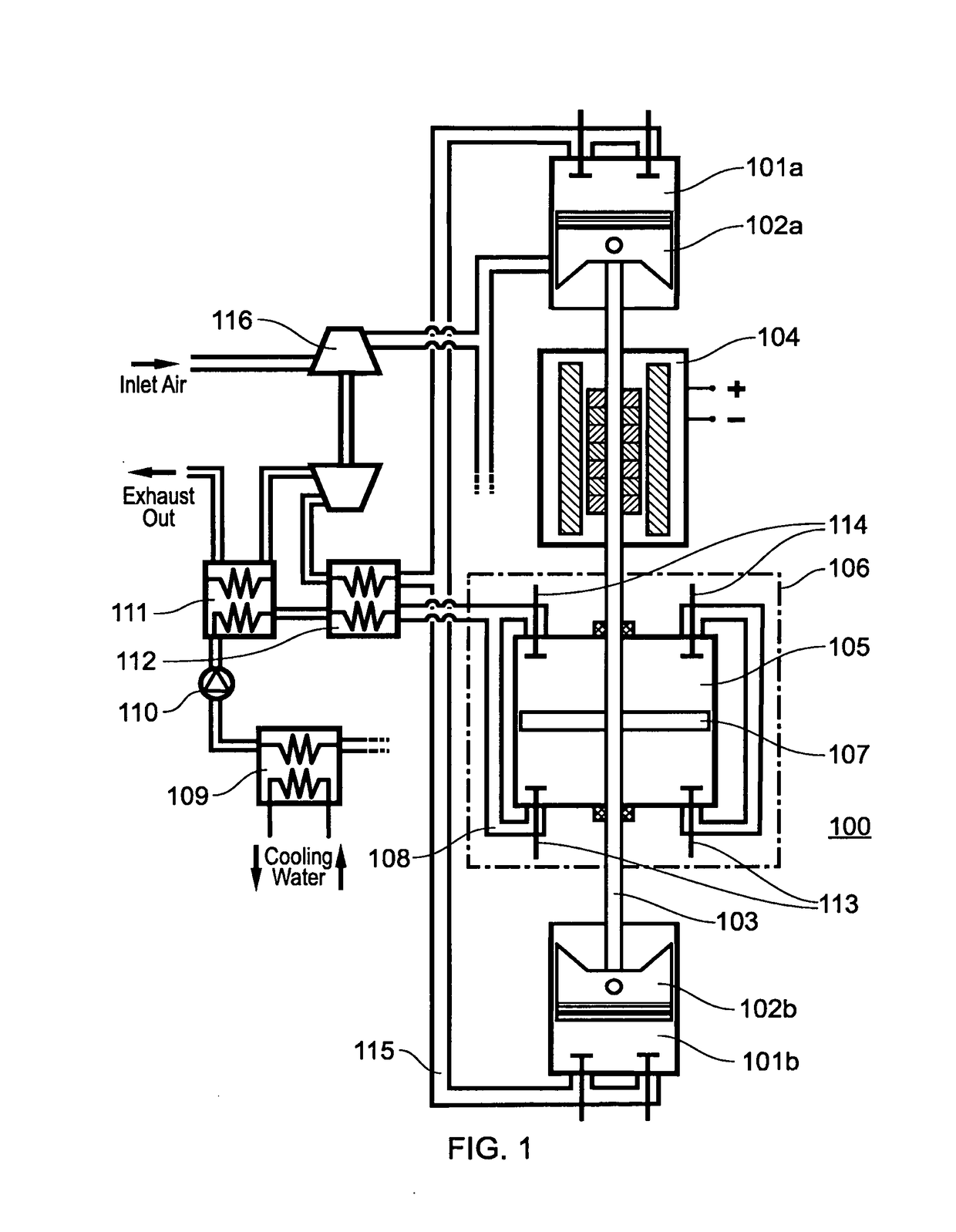
[0054]FIG. 1 shows a free-piston engine power plant 100. The free-piston engine power plant comprises two combustion cylinders 101a and 101b, each having an associated combustion piston 102a and 102b. The combustion pistons 102a and 102b are connected rigidly by shaft 103. Furthermore, the free-piston engine power plant comprises an electric machine 104, the electric machine having a translator fixed to the shaft 103 and a stator fixed in a stationary position relative to the shaft 103, for example, on the power plant housing (not shown).

[0055]When the combustion cylinders 101a and 101b operate alternately, the piston assembly is driven back and forth, and excess energy from the combustion cycles can be extracted through the electric machine.

[0056]The free-piston engine power plant 100 further comprises a bottoming cycle. In the embodiment shown in FIG. 1, this is a Rankine cycle. For the purposes of the FIG. 1, it shall be assumed that this is a water-based steam cycle, however oth...


PUM


Abstract

free-piston engine power plant incorporating a first combustion cylinder having a first combustion piston, a fluid expander having an expansion cylinder with an expander piston therein, the expander piston reciprocating in unison with the first combustion piston, a bottoming cycle having a working fluid and a heat exchanger.

Description

[0001]There is disclosed a free-piston engine power plant. In particular, there is disclosed a free-piston engine power plant incorporating means for improving control and efficiency of the free-piston engine.BACKGROUND[0002]Free-piston engines are linear engines, in which the reciprocating engine has substantially no rotating parts. Power take-out can be done via a linear energy conversion device, for example a linear electric generator or hydraulic pump, or via an exhaust gas turbine. A review of different free-piston engine configurations was presented in: Mikalsen R., Roskilly A. P; A review of free-piston engine history and applications; Applied Thermal Engineering, 2007; 27:2339-2352. An overview of some recent free-piston engine developments was presented in: Hanipah M. R., Mikalsen R., Roskilly A. P; Recent commercial free-piston engine developments for automotive applications; Applied Thermal Engineering, 2015; 75:493-503.[0003]A challenge in free-piston engines is the cont...

Claims


Application Information

Patent Timeline
Patent Type & Authority Applications(United States)
IPC IPC(8): F02G1/043F02B71/04
CPCF02G1/0435F02B71/04F02G2244/50F01B11/02F01K23/065F02G5/02F02B37/00F02B41/10F02B71/00F02B71/06F01B11/00F01B11/004Y02E20/14F01N5/04Y02T10/12
Inventor ROSKILLY, ANTHONY PAULMIKALSEN, RIKARD
Owner UNIVERSITY OF DURHAM
Why Eureka
Try Eureka