Method and apparatus for a high output sensor system

a high-output sensor and sensor technology, applied in the field of motion/movement sensors, detectors, monitors, etc., can solve the problems that the detection of low-frequency events has previously required significant amplification, and achieve the effect of small amounts of energy

Active Publication Date: 2006-08-10
SAPURAST RES
View PDF39 Cites 8 Cited by
  • Summary
  • Abstract
  • Description
  • Claims
  • Application Information

AI Technical Summary

Benefits of technology

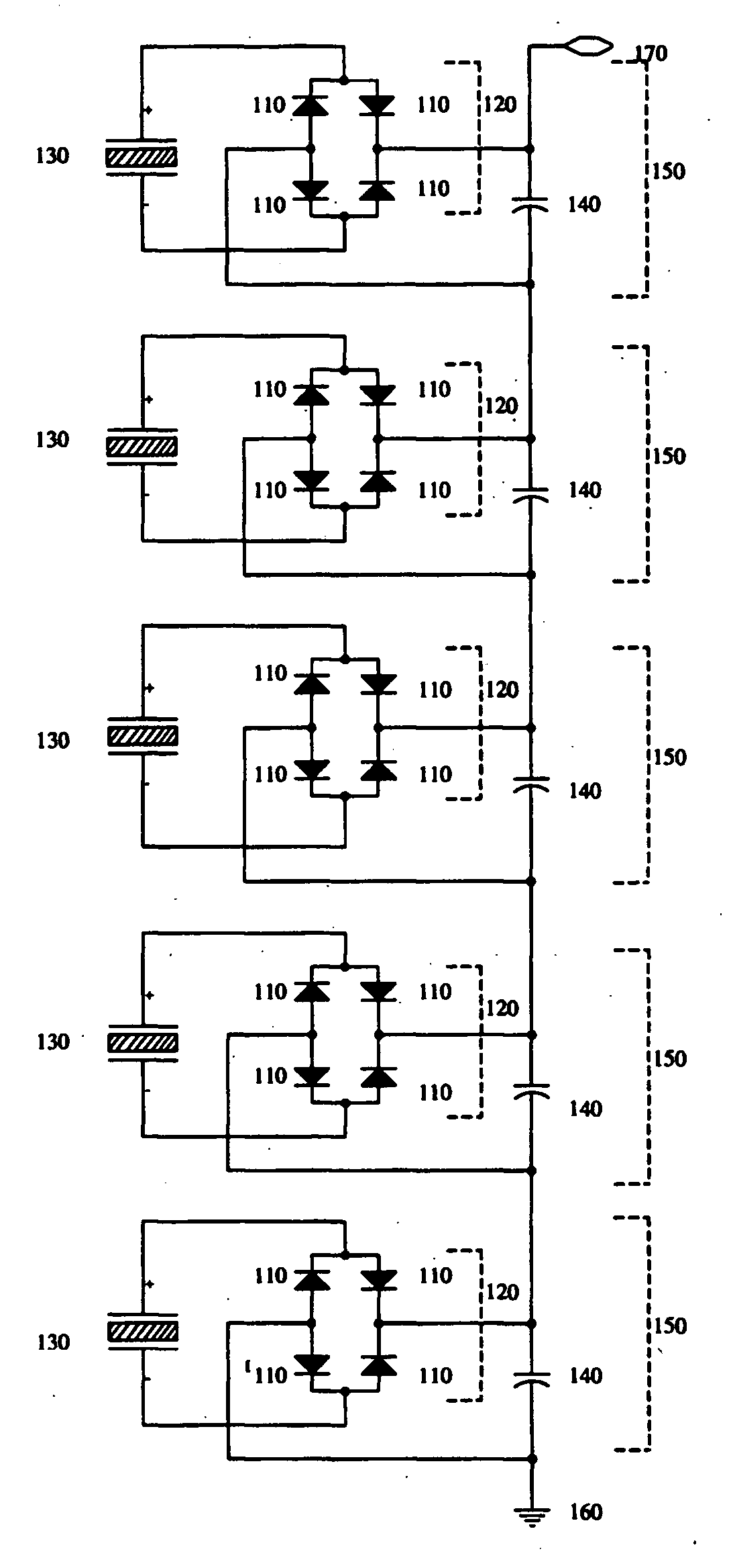
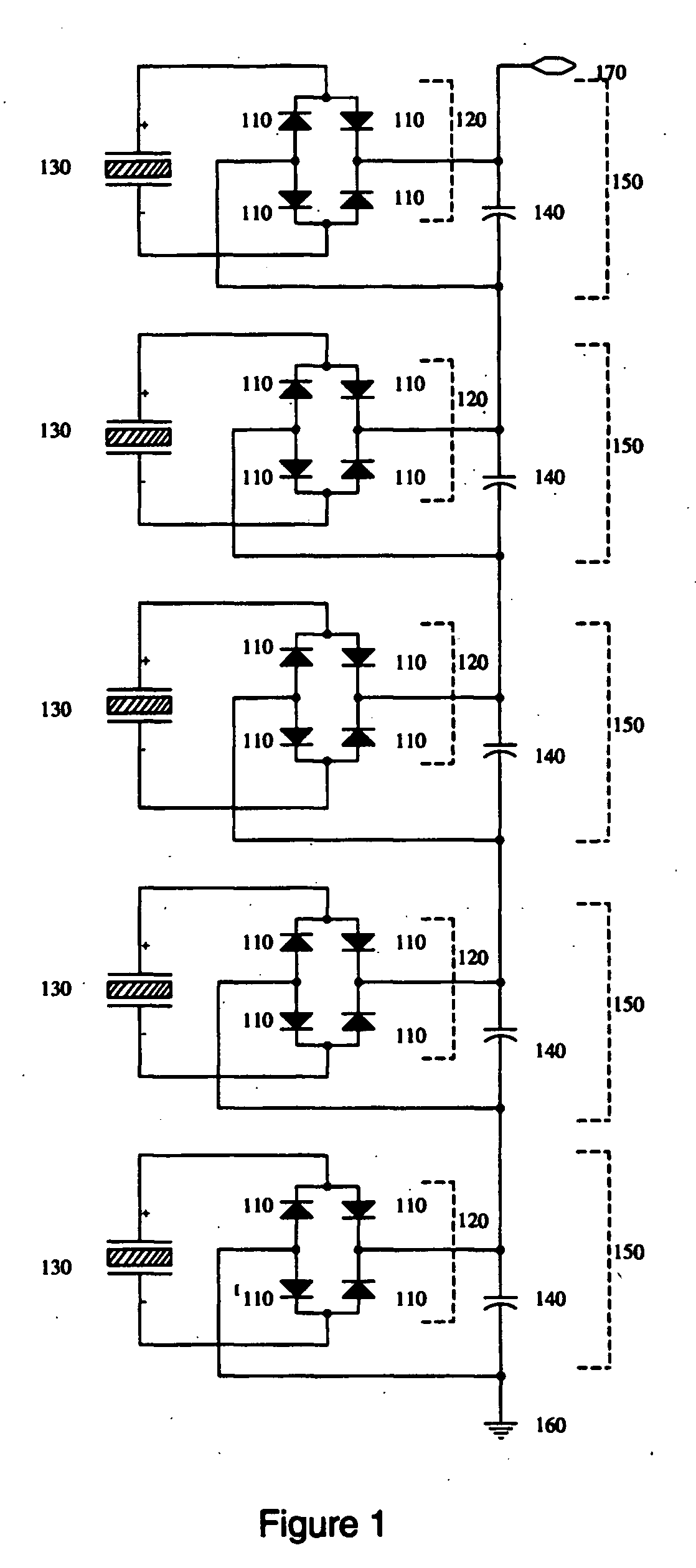
[0009] Another advantage of the present invention may be that the present invention may be adapted to operate when supplied with relatively small amounts of energy. An example energy source for this invention includes longitudinal stretch motion relative to the object on which an embodiment of the present invention may be mounted. This stretch may supply energy for longitudinal movements as small as 1.5 μm. Furthermore, in applications based on temperature change, the charge stacking characteristic of the present invention may output pulses based on a relatively small temperature change. In a stacked element array, the temperature change may be the same for all elements. For example, in a five-element stack, a 0.2° Celsius (one fifth degree) change may produce an approximate 8 volt open circuit output pulse. Thus, in an “n” element stack, a 1 / n Celsius change may produce an 8 volt open circuit output pulse.
[0010] An object of an embodiment of the present invention is to provide a sensing device that may be optimized for almost any event. It is another object of an embodiment of the present invention to provide a sensing device for robotic feeling. The present invention may be useful in robotic feeling applications because the sensor does not require energy to be expended when there is no sensation present. Additionally, the present invention may be capable of detecting very small or low frequency events. This detection capability may be useful for robotic tactile or other sensors for use in handling delicate or otherwise complex situations.
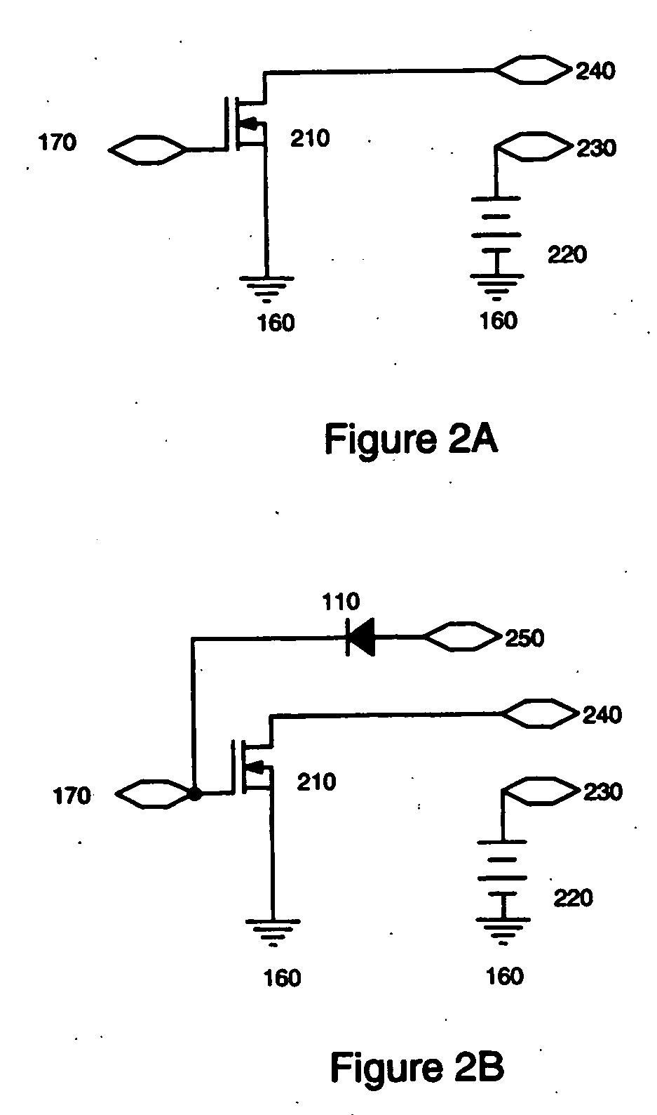
[0011] One embodiment of the present invention may be an apparatus for use as a sensor including a plurality of stacked piezoelectric elements, a rectification block on an output of each of the elements, and a plurality of capacitors arranged to accumulate charge from the rectification blocks. Moreover, in certain embodiments, a switching device may be connected to an output of the plurality of capacitors. Although the invention is described in terms of the use of capacitors, the invention may, for example, be implemented by other circuit components that have inherent capacitance. Thus, any element that has a useful capacitance may be considered a capacitive element.
[0012] In a particular embodiment of the present invention, the rectification block may be a full-wave rectification block or a half-wave rectification block. The apparatus may include two or more stacked piezoelectric elements. Moreover, in a further embodiment of the present invention, the apparatus may further include a signal phase delay element (such as, for example, an inductor) provided between the rectification blocks and the capacitors. In another particular embodiment of the present invention, the switch device may comprise a transistor or group of transistors.
[0013] The apparatus may be optimized to detect, monitor and / or sense changes in position of an item or structure upon which it is mounted. A door or window may be examples of such structures. Should the door or window be moved even slightly, the sensor of an embodiment of the present invention may provide an output. An appropriate angle to mount an embodiment of the present invention to the surface of the item or structure being monitored may be approximately perpendicular or approximately 90 degrees to the plane of movement to be monitored.
[0014] The apparatus of an embodiment of the present invention may be optimized for detecting, monitoring and / or sensing changes in position of an item or structure that it is placed upon it. Any item or structure that is placed upon the sensor of an embodiment of the present invention may provide a preload of the device that will be changed if the item or structure is moved from the initial position. An example of such an item to be monitored is a museum antiquity. If the antiquity is moved, the sensor may provide a desired output. The sensor of this embodiment of the present invention may also be configured to avoid certain forms of detection. For example, devices that constantly draw current may emit undesired electromagnetic radiation. This electromagnetic radiation can be “seen” by a variety of sensors. However, certain embodiments of the present invention may avoid such detection by not drawing any current (or drawing mere nanoamps) in an untriggered state, thus making detection less likely.

Problems solved by technology

Because a piezoelectric event generally produces only small amounts of energy, the detection of low frequency events has previously required significant amplification.

Method used


Image

  • Method and apparatus for a high output sensor system
  • Method and apparatus for a high output sensor system
  • Method and apparatus for a high output sensor system

Examples


Embodiment Construction

[0030] It is to be understood that the present invention is not limited to the particular methodology, compounds, materials, manufacturing techniques, uses, and applications, described herein, as these may vary. It is also to be understood that the terminology used herein is used for the purpose of describing particular embodiments only, and is not intended to limit the scope of the present invention. It must be noted that as used herein and in the appended claims, the singular forms “a,”“an,” and “the” include the plural reference unless the context clearly dictates otherwise. Thus, for example, a reference to “an element” is a reference to one or more elements and includes equivalents thereof known to those skilled in the art. Similarly, for another example, a reference to “a step” or “a means” is a reference to one or more steps or means and may include sub-steps and subservient means. All conjunctions used are to be understood in the most inclusive sense possible. Thus, the word...


PUM

PropertyMeasurementUnit
angleaaaaaaaaaa
piezoelectricaaaaaaaaaa
gravityaaaaaaaaaa

Abstract

The present invention relates to the field of motion / movement sensors, detectors, and / or monitors, as well as other types of sensors. In particular, the present invention may provide, for example, a large pulsed output voltage in response to very low (or slow) sensed movement or environment changes, such as, temperature, pressure, and energy. The present invention relates, for example, to other available sensors and may provide an output high enough to turn on related processing circuitry from an “OFF” state. The present invention relates, among other things, to sensing various events via, for example, axially poled homopolymer polyvinyladine fluoride (PVDF) or other piezoelectric materials.

Description

CROSS REFERENCE TO RELATED APPLICATIONS [0001] The present application is a continuation and claims the benefit under 35 U.S.C. §120 of U.S. patent application Ser. No. 10 / 762,278, filed 23 Jan. 2004, which is related to and claims the benefit under 35 U.S.C. §119 of U.S. provisional patent application Ser. No. 60 / 536,250, filed 14 Jan. 2004, which are expressly incorporated fully herein by reference.FIELD OF THE INVENTION [0002] The present invention relates to the field of motion / movement sensors, detectors, and / or monitors, as well as other types of sensors. In particular, the present invention may provide, for example, a large pulsed output voltage in response to very low (or slow) sensed movement or environment changes, such as, temperature, pressure, and energy. The present invention relates, for example, to other available sensors and may provide an output high enough to turn on related processing circuitry from an “OFF” state. The present invention relates, among other thing...

Claims


Application Information

Patent Timeline
Patent Type & Authority Applications(United States)
IPC IPC(8): H01L41/113G01D5/18G01L1/16H01L41/04H01L41/083H01L41/22H01L41/27H01L41/311H01L41/45
CPCG01D5/18H01L41/042H01L41/1132G01D5/185H10N30/802H10N30/302H10N30/50
Inventor BRANTNER, PAUL C.
Owner SAPURAST RES
Why Eureka
Try Eureka