Method for transmitting a digital signal for a marc system having a dynamic half-duplex relay, corresponding program product and relay device

a relay and digital signal technology, applied in the field of transmitting digital signals in a multiple access relay channel (marc) network, can solve the problems of reducing the coverage and thus the capacity of the system, difficult transmission channels of mobile networks, and reducing so as to maximize the use of common spectrum resources, increase the probability of being able, and prolong the non-selective listening time

Active Publication Date: 2016-11-17
ORANGE SA (FR)
View PDF6 Cites 5 Cited by
  • Summary
  • Abstract
  • Description
  • Claims
  • Application Information

AI Technical Summary

Benefits of technology

[0023]Below a threshold B1 for the number of uses of the transmission channel that have taken place, the relay remains in a non-selective listening mode. In this mode, the relay attempts to detect and decode without error the messages from all of the sources. As soon as a number of channel uses that have taken place exceeds the threshold B1, the relay passes into a selective listening mode. In this mode, the relay switches from a listening stage in which it attempts to detect and decode without error the messages from the sources to a stage of encoding and forwarding a message to the destination as soon as the message is decoded without error. Thus, the relay passes from non-selective listening to selective listening if the elapsed time exceeds the threshold B1, which constitutes a parameter of the system. The threshold B1 thus makes it possible to avoid penalizing sources that require more time for decoding than a source having a source-relay link that is considerably better than the source-relay links of the other sources. Setting the threshold B1 thus makes it possible to introduce operating flexibility into the MARC system that enables the relay to adapt to differing environments between the sources. B1 may be variable, e.g. for each B block codeword or as a function of some number of codewords. The listening time of the relay is not constant, unlike prior techniques that make use of a half-duplex relay in a MARC system. This flexibility makes it possible firstly to adapt to instantaneous variation in the quality of the source-relay links, which is not possible with prior art techniques. Furthermore, in the event of a link between one of the sources and the relay being very poor, lengthening the non-selective listening time can make it possible in the end for the relay to decode the source and forward a signal representative of the messages from all of the sources to the destination. Also, even if this source cannot be decoded without error, the relay can nevertheless assist the destination by forwarding a signal representative of the messages from the other sources that have been decoded without error after passing into the selective listening mode. Furthermore, this operation is completely transparent for the sources; only the relay adapts its listening mode.
[0024]Thus, the invention relies in particular on the distinction between two listening modes of the relay, a total listening mode and a selective listening mode. During the total listening mode, the relay waits to decode the messages from all of the sources without error on the basis, for any one source, of all or some of the received codewords transmitted by that source, before encoding and forwarding the messages that have been decoded without error. After passing from the total listening mode to the selective listening mode, the relay acts, after encoding, to forward the first message decoded without error. The switchover from a listening stage to an encoding and forwarding stage thus takes place dynamically and no longer at a fixed moment, as in the prior art selective relaying method. This flexibility of switchover enables the operation of the relay to be adapted to the quality of the channels between the sources and the relay, which is not possible if the listening time of the relay is constant relative to the duration of transmission from the sources. Unlike the prior art selective relaying method, the invention distinguishes between two listening modes that increase the probability of being able to decode a plurality of sources without error even when one of the source-relay links is of quality that is much better than the other links.
[0025]In an embodiment, the sources transmit simultaneously over the same radio resource, and the decoding step is iterative and comprises joint detection and joint decoding. The transmission by the sources takes place simultaneously over the same radio resource (time and frequency), which makes it possible to maximize use of the common spectrum resource; the source-relay links are not orthogonal. There is thus interference between the signals received by the relay and by the destination as a result of the source signals being superposed during transmission firstly between the sources and the relay and secondly between the sources and the destination. When the sources transmit simultaneously but on different spectrum resources, the relay does not need the iterative joint detection and decoding step. Under such circumstances, the relay can decode the messages from the sources on the basis of sequences received without interference between the sources.

Problems solved by technology

The transmission channel of a mobile network has the reputation of being difficult, and leads to transmission of reliability that is relatively poor.
Such reduction goes against the coverage and thus against the capacity of the system, and more generally against its performance.
Although the selective relaying technique presents undeniable advantages by avoiding error propagation by the relay, its use with a half-duplex relay has the drawback of requiring that the relay and the sources determine and know the respective durations of the two transmission stages.
There is thus interference between the signals received by the relay and by the destination as a result of the source signals being superposed during transmission firstly between the sources and the relay and secondly between the sources and the destination.

Method used


Image

  • Method for transmitting a digital signal for a marc system having a dynamic half-duplex relay, corresponding program product and relay device
  • Method for transmitting a digital signal for a marc system having a dynamic half-duplex relay, corresponding program product and relay device
  • Method for transmitting a digital signal for a marc system having a dynamic half-duplex relay, corresponding program product and relay device

Examples


Embodiment Construction

[0059]There is no constraint on the transmission channel; it may be subject to fast or slow fading, it may be frequency selective, and it may be a multiple-input and multiple-output (MIMO) channel. In the description below, it is assumed that the nodes of the MARC system are accurately synchronized and that the sources are independent (there is no correlation between them).

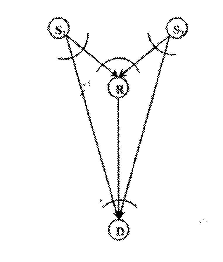
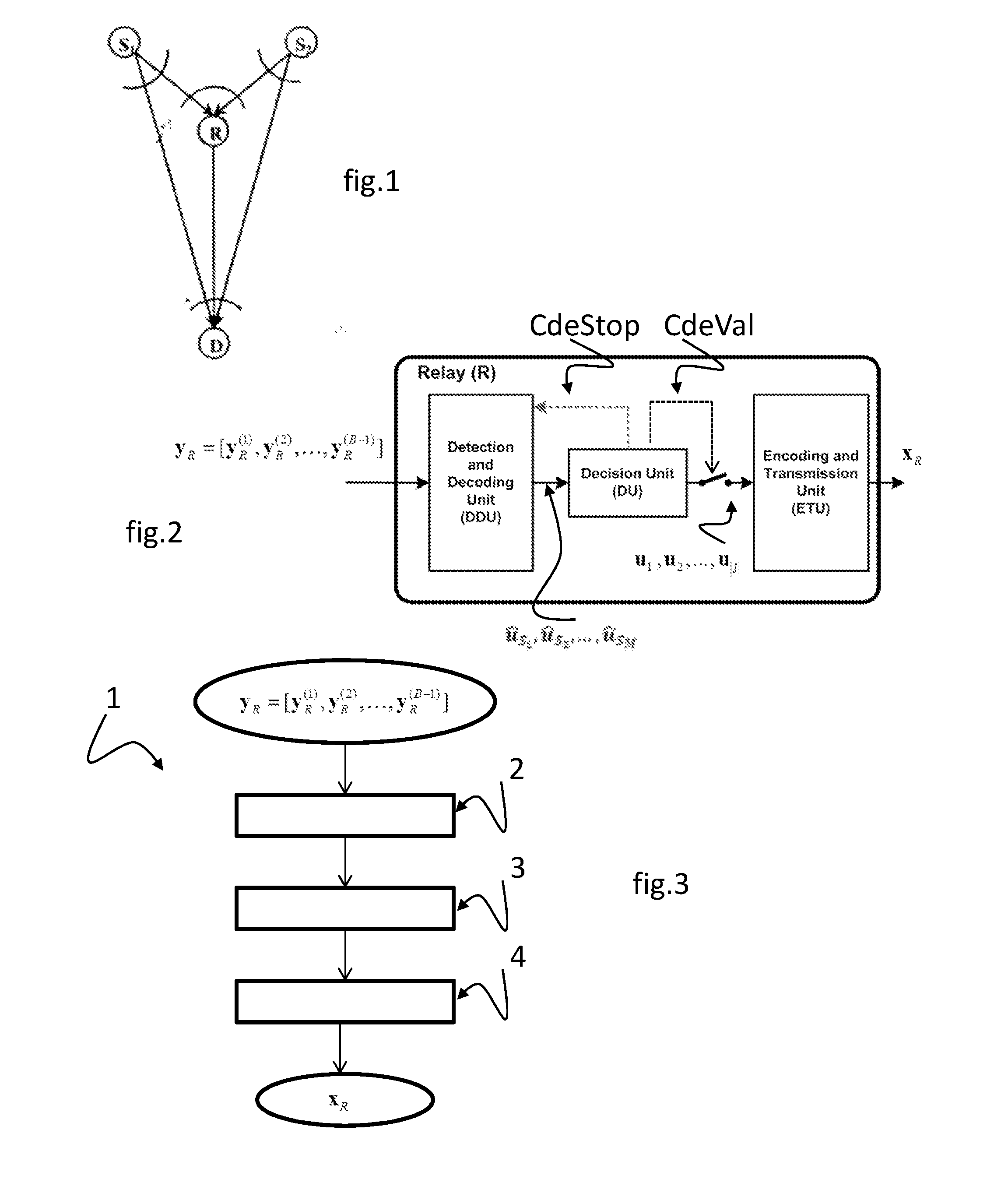
[0060]The invention lies in the context of a MARC system having M sources S1, S2, . . . , SM, one or more relays R, and a destination D. The sources and the relays are assumed to be provided with respective single transmit antennas in order to simplify the description. It should naturally be understood that the sources and the relays could be provided with respective pluralities of transmit antennas. The relays and the destination are assumed to be provided with respective single receive antennas in order to simplify the description, but it should naturally be understood that they may be provided with respective p...


PUM


Abstract

A relaying method performed by a half duplex relay for a telecommunications system. The method includes a reception stage of receiving codewords transmitted by a source, the successive codewords corresponding to B blocks, the first of which can be decoded independently of the other blocks. This stage includes a decoding step of estimating a message from each source based on received codewords, the message being associated with the codewords transmitted by the source. The relay performs an error detection and decision-taking step on messages that are decoded without error. The relay encodes a signal and forwards it to the destination, wherein the signal is representative of only those messages that are decoded without error, such that the relay passes from non-selective reception to selective reception after receiving B1 blocks and switches from the reception stage to the encoding and forwarding stage under control of the error detection and decision stage.

Description

CROSS-REFERENCE TO RELATED APPLICATIONS[0001]This Application is a Section 371 National Stage Application of International Application No. PCT / FR2014 / 053432, filed Dec. 18, 2014, the content of which is incorporated herein by reference in its entirety, and published as WO 2015 / 092302 on Jun. 25, 2015, not in English.FIELD OF THE DISCLOSURE[0002]The field of the invention is that of transmitting encoded data in a multiple access relay channel (MARC) network. A MARC network is a telecommunications system with at least four nodes having at least two sources (transmitters), a relay, and a destination (receiver). More precisely, the invention relates to network coding and it seeks to improve the quality of data transmission, and in particular to improve the performance of error-correcting decoding in a receiver.[0003]The invention relates particularly, but not exclusively, to transmitting data via mobile networks, e.g. for real-time applications.BACKGROUND OF THE DISCLOSURE[0004]Networks...

Claims


Application Information

Patent Timeline
Patent Type & Authority Applications(United States)
IPC IPC(8): H04L1/00H04L5/16H04L29/08H04B7/155
CPCH04L1/0041H04B7/15521H04L5/16H04L1/0061H04L1/0045H04L1/0057H04L69/324H04L1/005H04L1/1819H04L2001/0097H04L1/004H04L1/0077
Inventor MOHAMAD, ABDULAZIZVISOZ, RAPHAELBERTHET, ANTOINE
Owner ORANGE SA (FR)
Why Eureka
Try Eureka