Footwear having cushioning between sole and upper

a technology of sole and upper, applied in the field of shoes, can solve the problems of lateral “roll over” of the shoe, the stability and load distribution of the shoe may be particularly significant, and the stability and load distribution problems may be particularly significant, and achieve the effect of reducing certain disadvantages of the sho

Active Publication Date: 2018-05-08
DESMARAIS RICHARD PATRICK
View PDF26 Cites 0 Cited by
  • Summary
  • Abstract
  • Description
  • Claims
  • Application Information

AI Technical Summary

Benefits of technology

[0012]The present invention seeks to eliminate, or at least mitigate, certain disadvantages of shoes that provide a cushioning layer that is potentially subject to lateral and / or longitudinal instability, or at least provide an alternative.
[0020]In general, the ligatures may be angularly disposed to resist lateral displacement forces acting between the upper and sole of the shoe and unbalanced vertical compressive forces acting on said shoe. At least one of said ligatures may be oriented to angle outwardly and downwardly from an upper anchoring location adjacent to said central axis to a lower engagement location adjacent to an outer edge of said sole assembly. The downward / outward angling of the ligatures allows them to stabilize lateral movement of the sole relative to the upper. At least one of said ligatures may also extend substantially longitudinally between the front and rear ends of said shoe. At least two of the ligatures may extend in opposing directions substantially perpendicular to said central axis for purely lateral stability. At least one of said ligatures may be oriented in a direction intermediate between perpendicular and parallel to said central axis to provide stability against angled (non-perpendicular) horizontal forces acting on the shoe. The ligatures may also comprise two sets of ligatures wherein a first of said sets comprises ligatures that are anchored at or adjacent to the widest portion of the front of said shoe and a second of said sets is anchored at or adjacent to the widest portion of the rear of said shoe.
[0026]The midsole 28 may be provided with a plurality of ribs depending from its underside, each rib extending between a pair of holes either side of the upper boss. Each rib may have a curved profile so as to reduce the bending angle of the ligature as it passes through the hole. The curvature of the rib may help to distribute the load across the width of the lower midsole. The curved edge of each rib may be grooved to receive the ligature and reduce the likelihood of it sliding off the rib.

Problems solved by technology

Also, sports shoes used in, for example, basketball or other sports involving rapid changes in direction and stopping abruptly may stretch the material of the shoe upper and lead to problems with stability and load distribution of the shoe.
Stability and load distribution problems may be particularly significant in shoes which have a relatively thick and / or compliant cushioning section between the outsole and the insole.
Such problems can arise with cushioning of the kind comprising an air bag or bladder or a plurality of air pockets or cells distributed about the sole of the shoe between the outsole and the insole.
Both kinds of air cushioning members may be susceptible to lateral or axial instability which can lead to lateral “roll over” of the shoe, lateral instability or other problems during use.
Instability can also arise when the cushion is subjected to unbalanced vertical compressive forces.
However, in the absence of means to improve stability, a flexible sidewall tends to have less lateral stability which can increase the tendency of the shoe to roll over or for the sole to be displaced laterally or axially relative to the upper when subjected to horizontal stresses (lateral or axial) or imbalanced forces.
As a result of these competing requirements, shoe design often involves a trade-off or compromise between the requirements for stability and cushioning.
Although the use of strands for reinforcing the sidewalls of the shoe upper may make the shoe upper less stretchable, and air cell walls and / or hydraulic stabilizers may improve stability, the above-mentioned ways of providing cushioning and stability between an outsole and insole separated by an intermediate cushioning section, especially comprising an airbag / bladder, are not entirely satisfactory in that these structures can reduce the vertical compressibility of the sole, thereby reducing shock absorption.

Method used


Image

  • Footwear having cushioning between sole and upper
  • Footwear having cushioning between sole and upper
  • Footwear having cushioning between sole and upper

Examples


Embodiment Construction

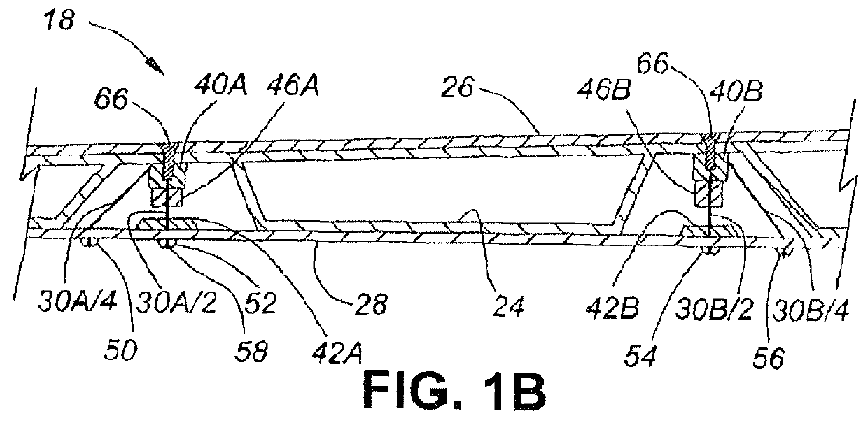
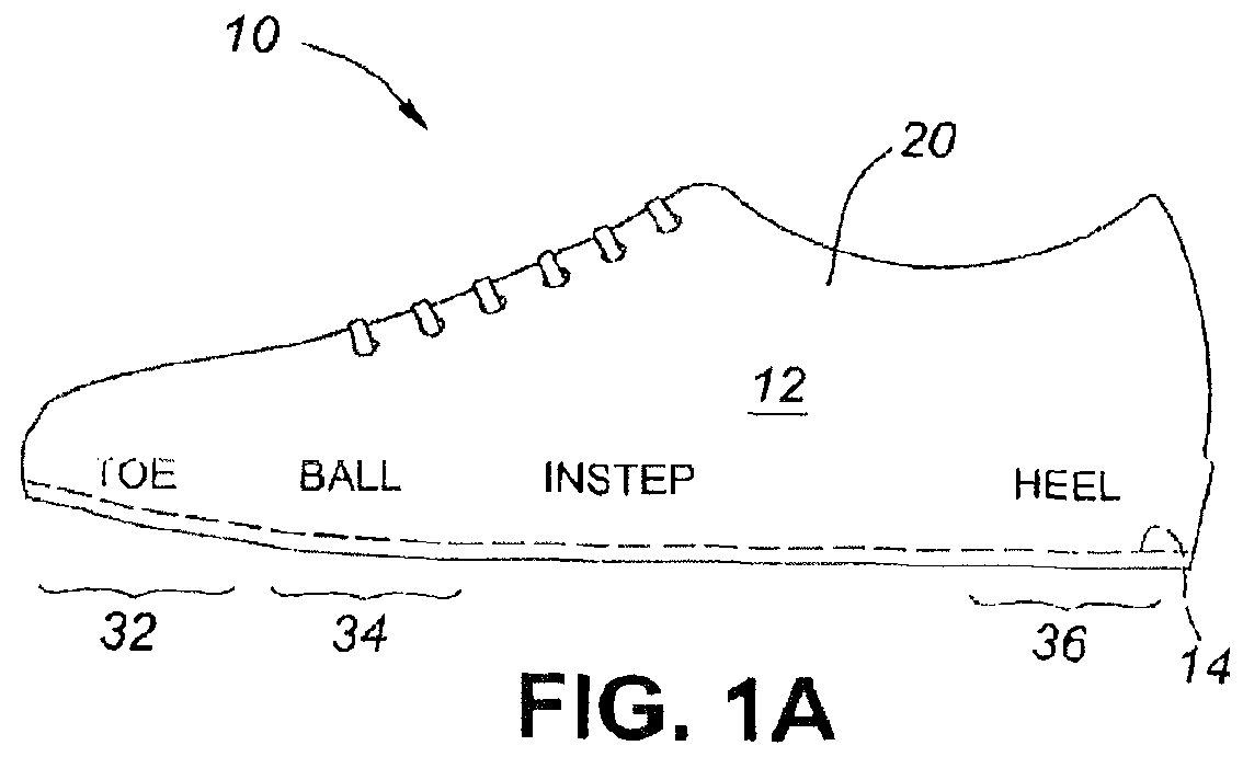
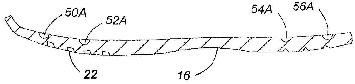
[0042]FIGS. 1A, 1B and 1C illustrate a running shoe 10 having a sole assembly according to the present invention. The shoe 10 comprises an upper body portion 12 attached to a sole assembly 11 (shown in exploded view in FIG. 3). Assembly 11 comprises an insole 14 (FIG. 1A) and an outsole 16 (FIG. 1c). The insole 14 and outsole 16 are spaced apart by a cushioning section 18. The insole 14 is attached at its periphery to the lower extremities of sidewalls 20 of the upper body portion 12 in a conventional way such as stitching and / or adhesive. As is common, the outsole 16 has a tread 22 on its lowermost surface which, in use, contacts the ground, and a small upturned front end. The outsole 16 may be made of conventional materials such as natural rubber, synthetic rubber, polyurethane, polyvinyl chloride or other suitable material; one example is marketed under the trade name Vibram™. The upper shoe body 12 usually will be made of natural or synthetic leather, nylon or other suitable mat...


PUM


Abstract

To provide cushioning and stability, a shoe has a sole section and an upper, the sole section comprising an outsole having a lower surface for contacting the ground, an insole and cushioning between the insole and the outsole. In addition, the shoe has a plurality of ligatures interconnecting the insole and the outsole, respectively, by way of the cushioning section. The ligatures control movement of the shoe upper relative to the outsole in at least two directions.

Description

CROSS-REFERENCE TO RELATED APPLICATION(S)[0001]This application claims priority to Canadian patent application no. 2,822,759, filed on Aug. 5, 2013. The contents of said application are incorporated by reference herein.TECHNICAL FIELD[0002]This invention relates to shoes such as athletic shoes having a cushioning layer such as an air bladder between the sole and the shoe upper.BACKGROUND[0003]For convenience, in this patent specification, the term “shoe” will be used for an article of footwear that includes a cushioned sole. Examples include athletic shoes such as running shoes, soccer / football shoes, basketball shoes, baseball shoes, cross-training shoes, cycling shoes or tennis shoes. The term can also refer to hiking boots, dress shoes, loafers, sandals, work boots and specialized footwear that includes a cushioned sole. Moreover, in the context of this specification, the term “shoe” embraces articles of footwear having a sole assembly comprising an outsole which contacts the gro...

Claims


Application Information

Patent Timeline
Patent Type & Authority Patents(United States)
IPC IPC(8): A43B13/20A43B13/18A43B13/14
CPCA43B13/203A43B13/14A43B13/20A43B13/186A43B13/181
Inventor DESMARAIS, RICHARD
Owner DESMARAIS RICHARD PATRICK
Why Eureka
Try Eureka