Eureka AIR delivers breakthrough ideas for toughest innovation challenges, trusted by R&D personnel around the world.

Rail vehicle comprising snow plow

Inactive Publication Date: 2018-05-08
SIEMENS MOBILITY GMBH
View PDF13 Cites 1 Cited by
  • Summary
  • Abstract
  • Description
  • Claims
  • Application Information

AI Technical Summary

Benefits of technology

The invention provides a rail vehicle with a snow plow that can adjust the gap between the snow plow and the running rails. This ensures that the snow plow does not interfere with the running of the rail vehicle and that components behind the snow plow are protected. The snow plow can also be adjusted to protect components in front of the snow plow. Additionally, the invention includes a deflection web on the blade plates to reduce the amount of snow thrown up from the blade plates onto a front window pane of a driver's cab. Furthermore, the snow plow includes lifting points that allow it to be easily lifted without disassembly. The invention also includes an integrated bracket for additional protection of the antenna device.

Problems solved by technology

Thus the blade plates are arranged too high most of the time.

Method used


Image

  • Rail vehicle comprising snow plow
  • Rail vehicle comprising snow plow
  • Rail vehicle comprising snow plow

Examples


Embodiment Construction

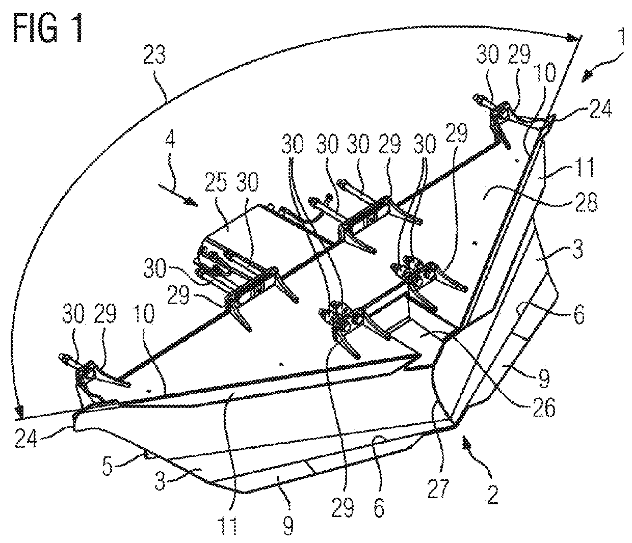
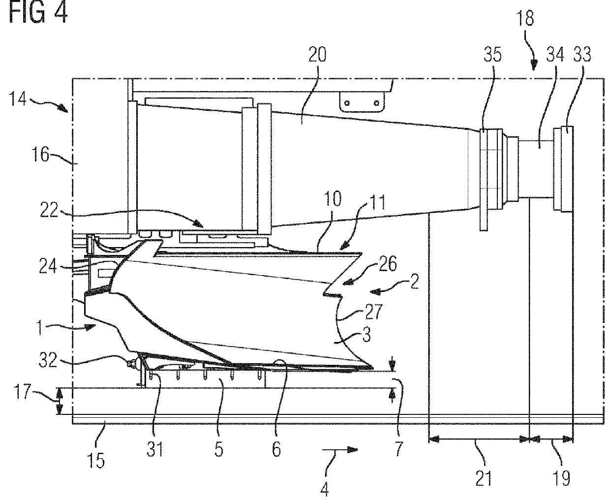
[0026]According to FIG. 1 to FIG. 4 a snow plow 1 comprises, for an inventive rail vehicle 14, in particular for a locomotive, two plow-shaped blade plates 3 running to a point 2, which form a first clearance stage. The blade plates 3 have a C-shaped profile and are arranged in a swept-back manner such that their concave front sides point in the direction of travel 4 of the rail vehicle 14. The straight lower edges 6 of the blade plates 3 lie on a base plate 8 of the snow plow 1, wherein the base plate 8 forms a cutting edge 9 projecting from the lower edges 6 in the direction of travel 4. A deflection web 11 projecting in the direction of travel 4 is integrally formed on an upper edge 10 of the blade plates 3. The blade plates 3 arranged so as to sweep back encompass an obtuse point angle 23 which lies in the range between 110° and 120°. At the point 2 both the blade plates 3 abut one another and form a common nose cutting edge 27. At their upper edges 10 the blade plates 3 are cut...


PUM


Abstract

A rail vehicle has a vehicle body supported in a sprung fashion on bogies. A snow plow has two blade plates that run to a point and a plow blade arranged vertically adjustably behind the blade plates. A projecting portion of the plow blade that projects downwards beyond a lower edge of the blade plates is adjustable. The blade plates rest with their lower edge on a base plate which forms a cutting edge that protrudes from the lower edge in the direction of travel. The snow plow is attached to an under frame of the vehicle body such that the base plate maintains a safety distance from the travel rails. The safety distance is predefined by a maximum spring compression of the vehicle body. The protruding portion of the plow blade is set as a function of the safety distance and of a wear of the wheels of the bogies.

Description

BACKGROUND OF THE INVENTION[0001]Field of the Invention[0002]The invention relates to a rail vehicle, in particular a locomotive, with a vehicle body which is supported in a sprung fashion on bogies that can travel along running rails, and a snow plow which has two blade plates that run to a point in a plow shape and have a C-shaped profile, and with a plow blade that is arranged in a vertically adjustable fashion behind the blade plates in the direction of travel, and whose projecting portion, which projects downward beyond a lower edge of the blade plates, is adjustable. The blade plates rest with their lower edge on a base plate, which forms a cutting edge that protrudes from the lower edge in the direction of travel.[0003]It is known for rail vehicles, in particular locomotives, to be fitted with snow plows, in order to clear snow of different thickness from the route up to a maximum height of 800 mm to 1000 mm above the running rails at running speeds of over 100 km / h, where po...

Claims


Application Information

Patent Timeline
IPC IPC(8): E01H5/06B61F19/04E01H8/04B61F19/06
CPCE01H5/061E01H8/04B61F19/06B61F19/04
Inventor FEGE, ALEXANDERMELDE, JOERGMEYER, JOACHIMPFORR, JOERG
Owner SIEMENS MOBILITY GMBH
Why Eureka
Eureka Blog
Learn More