Organic electroluminescent lighting device

a lighting device and electroluminescent technology, applied in the direction of organic semiconductor devices, semiconductor devices, electrical devices, etc., can solve the problems of uneven illumination and inability to achieve light emission in some cases, and achieve the effect of large surface light emission area and effective surface light emission

Active Publication Date: 2018-05-08
YAMAGATA UNIVERSITY +1
View PDF13 Cites 3 Cited by
  • Summary
  • Abstract
  • Description
  • Claims
  • Application Information

AI Technical Summary

Benefits of technology

[0014]According to such an auxiliary electrode, the pattern of the auxiliary electrode becomes less remarkable by particle scattering of light, and also the light extraction efficiency is enhanced.
[0020]According to such a Printing scheme, even in the case of a fine pattern shape, it is possible to form the auxiliary electrode and the interlayer insulating coating film accurately and efficiently.
[0024]Therefore, according to the organic EL lighting device of the present invention, the light extraction efficiency from the side of the transparent electrode substrate provided with the auxiliary electrode and the like is enhanced, and it is possible to effectively achieve surface light emission with a large area.

Problems solved by technology

For this reason, when the distance between the transparent electrode and a power supply unit increases, an electric current is not sufficiently supplied thereto due to wiring resistance, and thus a problem arises in which luminance unevenness occurs.
However, in the organic EL element manufactured as described above, when the formation of the coating film of the organic layer including the light-emitting layer on the auxiliary electrode, particularly, on the edge portion of the pattern, is not sufficient, short occurs between negative electrodes to be formed on the organic layer so that the electric current is concentrated on this portion, and thus a problem arises in which light emission may not be achieved in some cases.

Method used


Image

  • Organic electroluminescent lighting device

Examples


example 1

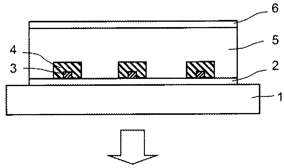
[0099]An organic EL lighting device (panel) having a configuration as illustrated in FIG. 1 was manufactured as follows.

[0100]A glass substrate was used as the translucent substrate 1, an ITO film was then formed, as the translucent electrode layer 2, on the glass substrate, and patterning was performed by photolithography, thereby forming a transparent electrode pattern.

[0101]Further, a silver ink obtained by dispersing silver particles having a particle diameter of 0.8 μm in an epoxy resin was printed on the substrate by a gravure offset scheme, thereby forming the auxiliary electrode 3. A printing plate having a depth of 10 μm and a line width of 50 μm was used.

[0102]An insulating ink (refractive index of about 1.6) comprised of an epoxy resin containing a phenolic resin as a curing agent was subjected to screen printing such that the insulating ink covered the contact portion between the auxiliary electrode 3 and the translucent electrode layer (ITO) 2 (that is, covered the circ...

example 2

[0106]An organic EL lighting panel was manufactured in the same manner as in Example 1, except that 1% by weight of titanium oxide particles having a particle diameter of 0.25 μm was added to the insulating ink in Example 1, and the luminance measurement was performed.

[0107]The luminance of the portion of the auxiliary electrode was ⅔ of the light-emitting portion on ITO, and the luminance of the portion of the interlayer insulating coating film was ⅖ of the light-emitting portion on ITO.


PUM


Abstract

Provided is an organic electroluminescent lighting device which can be seen that the entire surface is uniformly illuminated from the side of a transparent electrode substrate even when an auxiliary electrode or an auxiliary wiring is provided with respect to the transparent electrode substrate.In an organic electroluminescent lighting device including a pair of electrode layers including a translucent electrode layer provided on a translucent substrate, at least one organic layer interposed between the pair of electrode layers and including a light-emitting layer, and an auxiliary electrode provided on the translucent electrode layer such that the auxiliary electrode comes in contact with a portion of the translucent electrode layer, the auxiliary electrode includes conductive metal particles having a particle diameter of 0.1 to 2 μm, and is covered with an interlayer insulating coating film for suppressing the conduction with the organic layer.

Description

BACKGROUND OF THE INVENTION[0001]Technical Field[0002]The present invention relates to an organic EL lighting device having an organic electroluminescent element (hereinafter, abbreviated as the organic EL element) as a light emission source.[0003]Description of the Related Art[0004]The commercialization of the organic EL lighting device as a planar light source, which is a thin film and can achieve light emission with high luminance by driving at a low voltage, is progressing.[0005]When the light-emitting surface of the organic EL lighting is intended to be increased in area, the resistance value of a transparent electrode of ITO or the like which is generally used in the organic EL element is limited to be about 1.0×10⁻⁴ Ω·cm, and it cannot be said that this value is sufficiently low. For this reason, when the distance between the transparent electrode and a power supply unit increases, an electric current is not sufficiently supplied thereto due to wiring resistance, and thus a p...

Claims


Application Information

Patent Timeline
Patent Type & Authority Patents(United States)
IPC IPC(8): H01L29/08H01L29/04H01L27/14H01L51/52
CPCH01L51/5268H01L51/5212H01L2251/301H01L2251/558H01L2251/5361H01L2251/5392H01L2251/303H10K50/814H10K50/854H10K2102/00H10K2102/341H10K2102/351
Inventor FURUKAWA, TADAHIROKOBAYASHI, HIDEYUKIKAWAMURA, NORIFUMIOKAMOTO, TOMOKOSENTE, YASUHIROKATAYAMA, YOSHINORI
Owner YAMAGATA UNIVERSITY
Why Eureka
Try Eureka